Door handle sanitizer system and apparatus

a sanitizer system and door handle technology, applied in the field of apparatus and methods, can solve the problems of people's unwillingness to use public restrooms, unavoidable use, and near unavoidable touching a surface of the restroom

Inactive Publication Date: 2006-07-13
HYSO TECH
View PDF37 Cites 79 Cited by
  • Summary
  • Abstract
  • Description
  • Claims
  • Application Information

AI Technical Summary

Benefits of technology

[0011] These and further aspects, features and advantages of the present invention will become more apparent from the following detailed description w

Problems solved by technology

Many people are reluctant to use public restrooms due to actual or perceived sanitary conditions of those restrooms.
However, in some instances, such use is unavoidable.
However, touching a surface of the restroom is nearly unavoidable because sometimes the person must touch the handle of the door to exit the restroom.
All of these techniques work, but are burdensome and not efficient.
Covering a door handle, while effective in preventing a person from contacting the door handle during operation of

Method used


Image

  • Door handle sanitizer system and apparatus
  • Door handle sanitizer system and apparatus
  • Door handle sanitizer system and apparatus

Examples


first embodiment

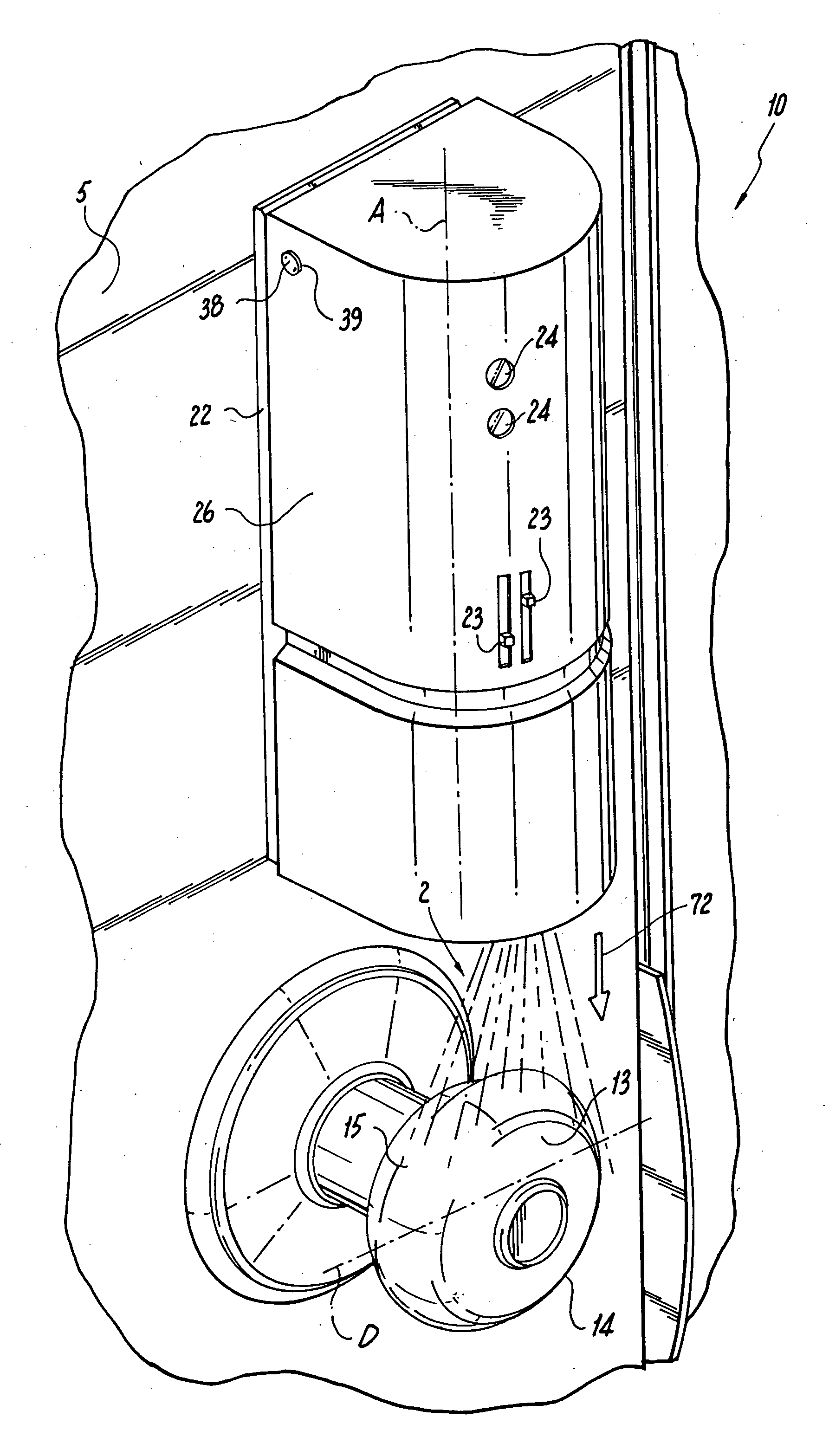
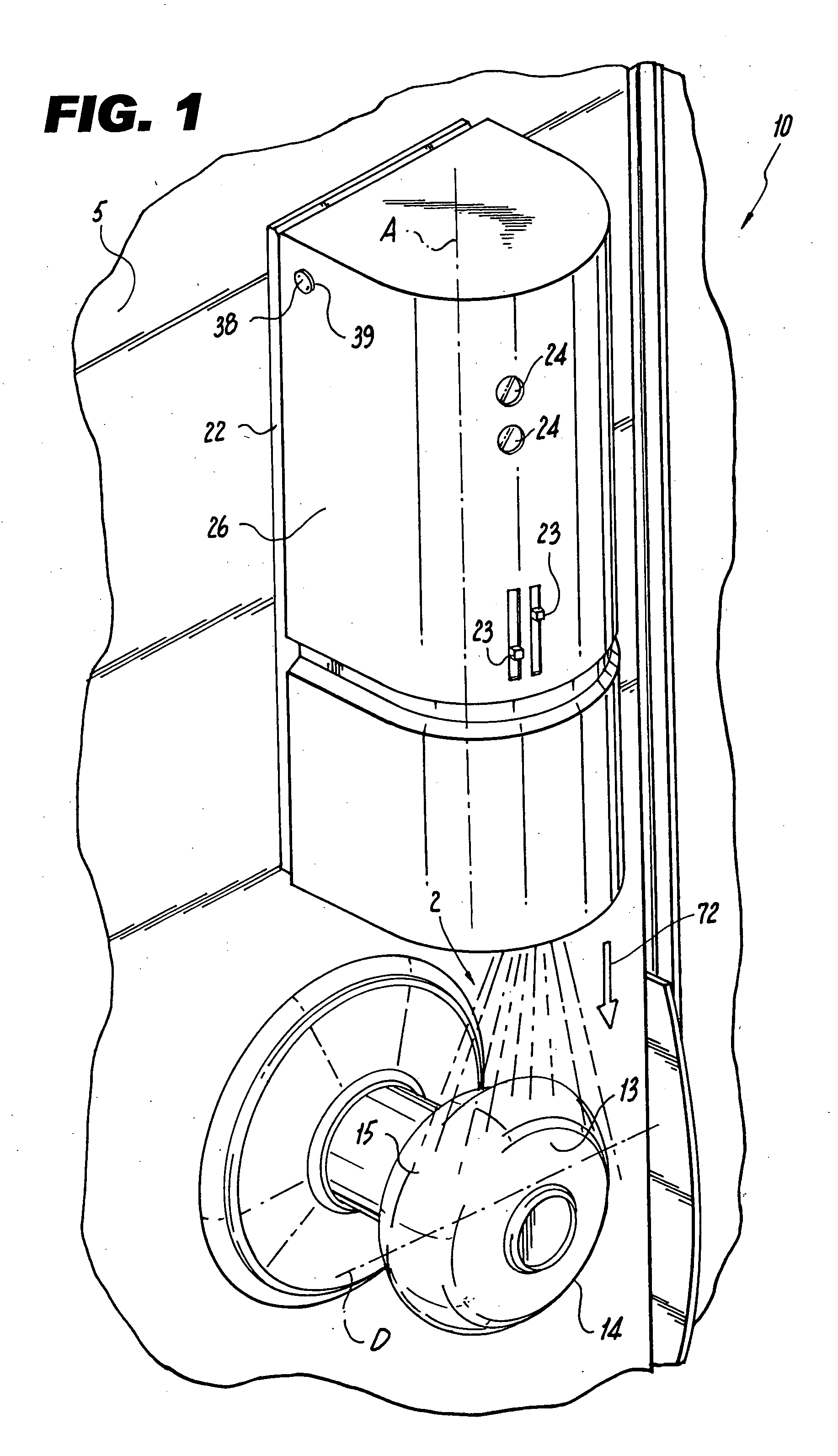
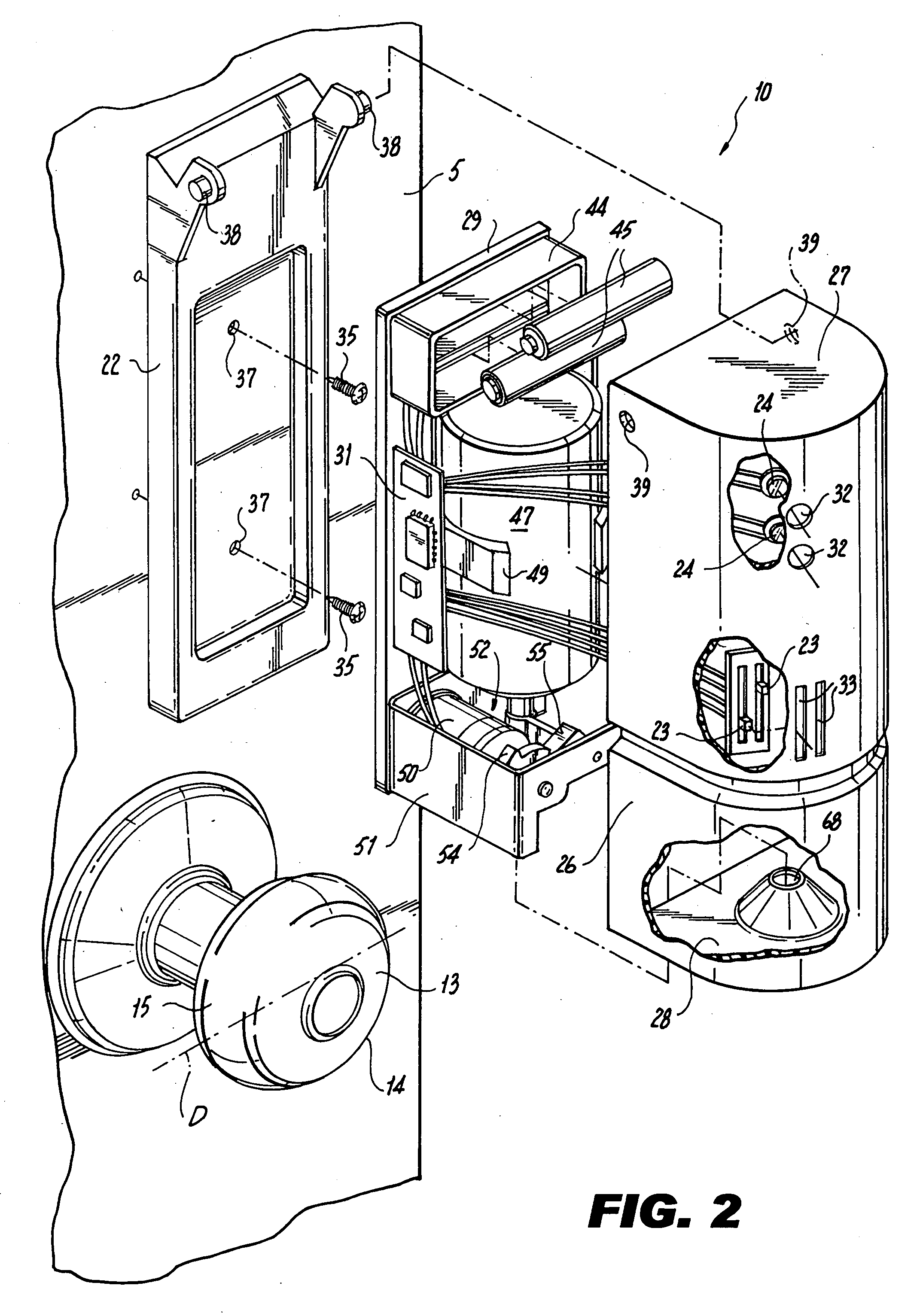
[0021]FIG. 1 illustrates a perspective view of a door 5 equipped with a spray dispenser 10 in accordance with the present invention. Spray dispenser 10 is operable to spray a germicide 2 therefrom to coat, and thereby sanitize, an outwardly extended door handle 14. FIG. 2 illustrates an exploded view of the dispenser 10.

[0022] Referring to FIGS. 1 and 2, spray dispenser 10 includes an outer housing 21, base 22, user accessible control switches 23 and visible indicator lights 24 for providing control and status information of dispenser 10.

[0023] Spray dispenser 10 is preferably mounted to door 5 above door handle 14 as indicated. Outer housing 21 is hingedly connected to base 22 via prongs 38. Prongs 38 are configured to fit through orifices 39 of housing 21 and allow for rotational movement of the outer housing 21 between a close and opened position. In a closed position, outer housing 21 completely conceals the internal components of dispenser 10, while in an opened position, oute...

second embodiment

[0037] Referring to FIG. 9, according to a door handle sanitizer, front wall 26 further comprises a sensor 95 for triggering spray actuator 52. Sensor 95 can be optical, infrared, mechanical / electrical or a combination of the above. Thus, in this arrangement the actuator 52 can activate the spray when a person or movement is detected in a vicinity of the handle or when a light beam interruption or vibration is detected.

[0038] Referring to FIG. 1, handle 14 can take any shape or size and is preferably configured to assist in opening and closing of door 5. Handle 14 can be of a stationary type used to push or pull door 5 or can be mechanically mounted and include a conventional locking mechanism, requiring rotation of a handle to unlock the door prior to opening and closing. While the handle is illustrated as a conventional cylindrical shaped door handle, the spray dispenser 10 described herein is operable to sanitize any door handle and examples of several handle shapes which can be ...


PUM


Abstract

An apparatus and method for sanitizing door handles includes dispensing a germicide, such as a disinfectant, antibacterial solution or cleansing agent, onto a door handle at controlled intervals. The door handle sanitizer further includes a source of liquid or gaseous disinfectant, a spray nozzle configured to convey liquid or gaseous disinfectant from the source to the nozzle and for dispensing the liquid or gaseous disinfectant onto the handle, and a controller for causing the liquid or gaseous disinfectant to be conveyed to the handle in intervals, wherein the intervals are responsive to an external condition and the controller if free of any manual activation.

Description

PRIORITY [0001] This application claims the benefit of U.S. Provisional Application Ser. No. 60 / 642,792, filed Jan. 10, 2005.FIELD OF THE INVENTION [0002] The present invention relates to an apparatus and method for rendering germ-free (sanitizing) door handles, and more particularly, to a device for dispensing a germicide, such as a disinfectant, antibacterial solution or cleansing agent, onto a door handle at controlled intervals. BACKGROUND OF THE INVENTION [0003] Many people are reluctant to use public restrooms due to actual or perceived sanitary conditions of those restrooms. However, in some instances, such use is unavoidable. [0004] These people try to avoid touching any surface after they have washed their hands. However, touching a surface of the restroom is nearly unavoidable because sometimes the person must touch the handle of the door to exit the restroom. Some people carry gloves, wipes or the like to use in such public restrooms. Some people take an extra paper towel...

Claims


Application Information

Patent Timeline
IPC IPC(8): A61L2/18B67D7/08
CPCA61L2/18A61L2/20A61L2/22A61L2/24B65D83/26B65D83/262B65D83/384B65D83/7575E05B1/0069
Inventor SASSOON, SIMON
Owner HYSO TECH
Why Eureka
Try Eureka