
Tape rule having reoriented measuring blade

Inactive Publication Date: 2006-07-20
STEVEN W LEWIS +1
View PDF4 Cites 1 Cited by
  • Summary
  • Abstract
  • Description
  • Claims
  • Application Information

AI Technical Summary

Benefits of technology

[0002] Accordingly, it is the broad object of the present invention to provide a novel coilable tape rule wherein the casing provides stable support and enables self-standing positioning, with the blade extended, with minimal concern for inadvertent displacement from a selected location.

Problems solved by technology

Even if the casing has straight, flat edge sections on which it can be supported, therefore, standing the casing on edge (as must be done if the indicia on the face of the blade are to be visible) affords a very low level of stability.
If left unattended, there is a likelihood that the rule casing will tip over, particularly if the extended blade is disturbed in any way, thus not only making it difficult to read the distance scale but, indeed, making the measurement itself unreliable due to displacement of the rule from its original position.

Method used


Image

  • Tape rule having reoriented measuring blade
  • Tape rule having reoriented measuring blade
  • Tape rule having reoriented measuring blade

Examples


Embodiment Construction

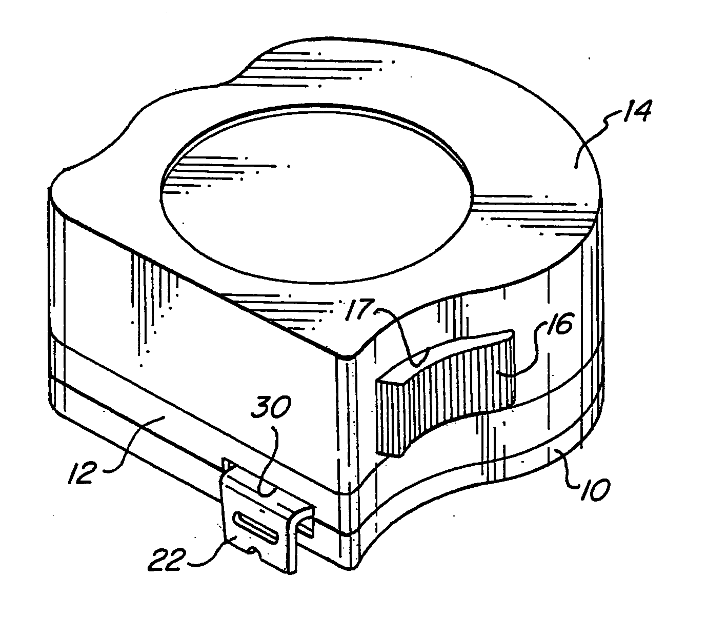
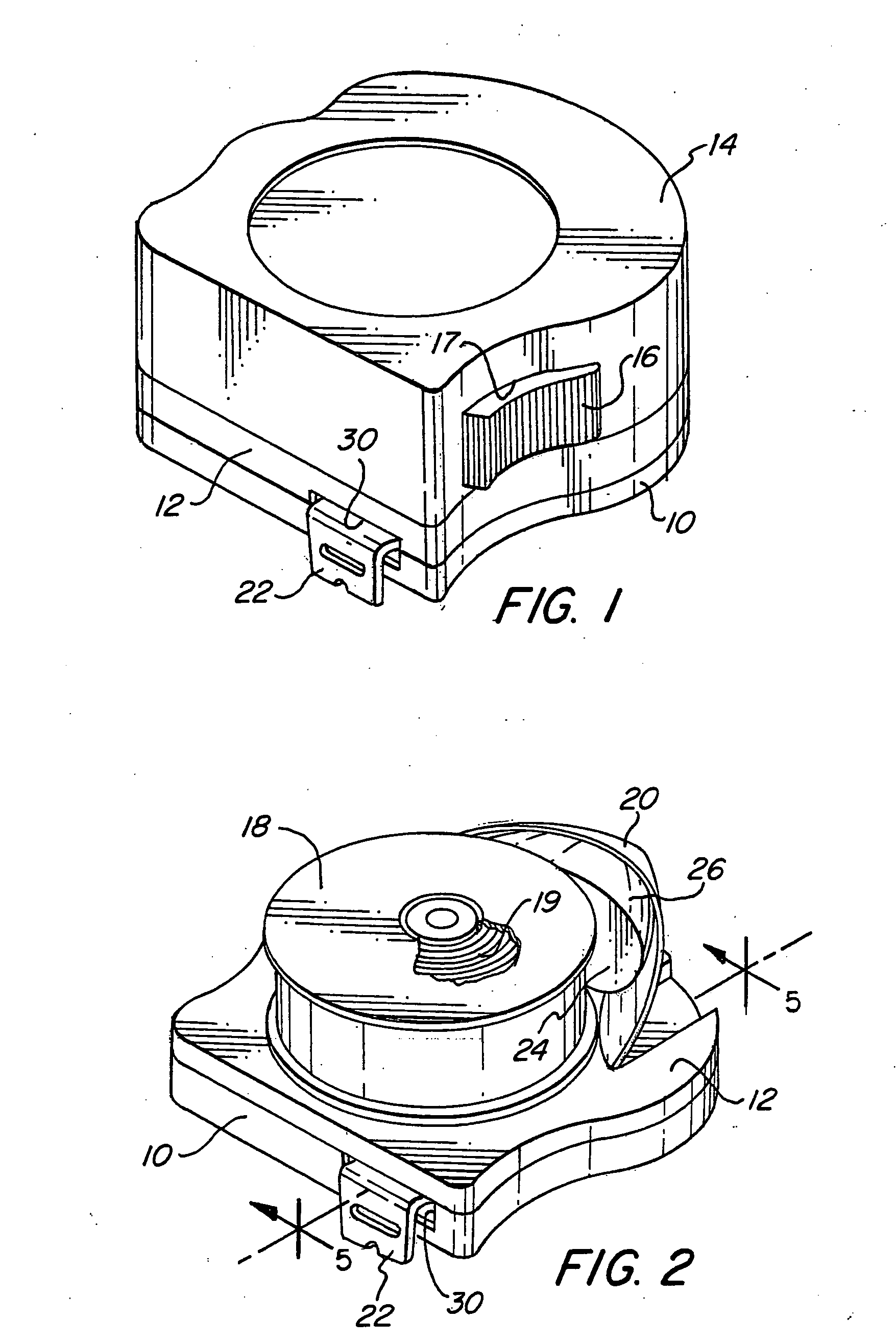
[0018] Turning initially to FIGS. 1 through 5 of the drawings, therein illustrated is a first form of coilable tape rules embodying the present invention and consisting of a casing base, comprised of an outer wall 10 and an inner plate 12, and a casing cover 14. A slide 16 for operating the brake mechanism (not illustrated) projects through an opening 17 defined in the peripheral wall of the cover 14, which brake mechanism serves of course to maintain the blade 20 in selected positions of extension against the retractive force of the power-return spring 19, constantly applied to the spool 18 on which the blade 20 is wound. The blade 20 is of course of great length relative to its width dimension, taken with respect to which dimension it is of concavo-convex cross-sectional form, as is conventional; it also terminates in a standard engagement hook 22.

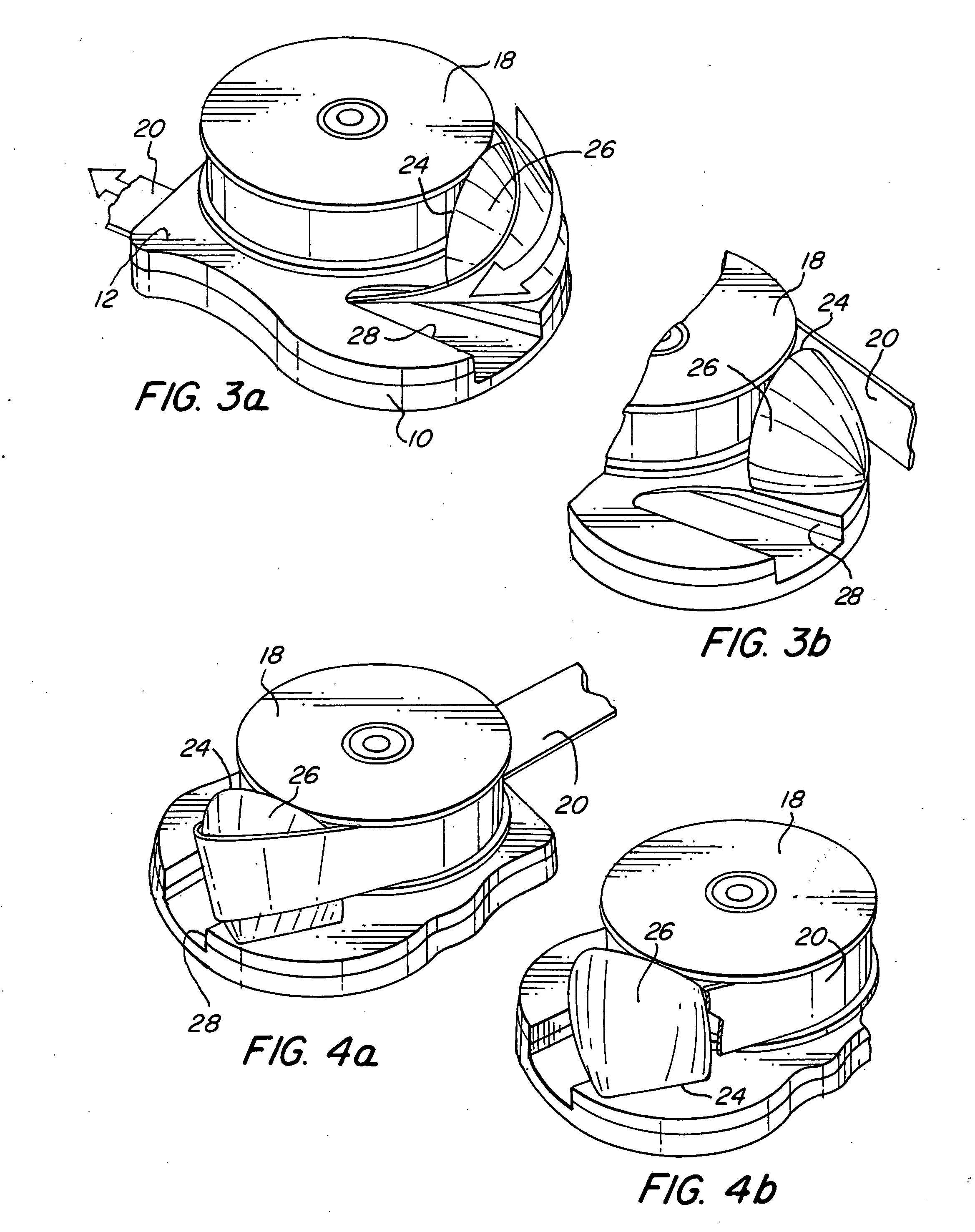
[0019] As is perhaps best seen in FIGS. 3 through 5 of the drawings, upon passage from the spool 18 the measuring blade 20 wraps parti...


PUM


Abstract

A coilable tape rule includes a fixed structure or a roller about which the measuring blade moves during extension from the casing and which causes the blade to turn on its longitudinal axis so as to reorient its width dimension to a perpendicular relationship to the axis of coiling.

Description

BACKGROUND OF THE INVENTION [0001] It is often desirable to place the casing of a tape rule at a certain position with the measuring blade extended so as to enable measurements to be made at remote locations, and to do so without need for holding the casing. In the conventional tape rule the blade pays out through a peripheral aperture, and is oriented with its width dimension corresponding to that of the casing. Even if the casing has straight, flat edge sections on which it can be supported, therefore, standing the casing on edge (as must be done if the indicia on the face of the blade are to be visible) affords a very low level of stability. If left unattended, there is a likelihood that the rule casing will tip over, particularly if the extended blade is disturbed in any way, thus not only making it difficult to read the distance scale but, indeed, making the measurement itself unreliable due to displacement of the rule from its original position. SUMMARY OF THE INVENTION [0002]...

Claims


Application Information

Patent Timeline
IPC IPC(8): G01B3/10
CPCG01B3/1041G01B3/1071G01B2003/1048G01B2003/1074G01B3/1048
Inventor LEWIS, STEVEN W.BRASS, ROBERT L.FREGA, JOHN F.
Owner STEVEN W LEWIS
Features
  • Generate Ideas
  • Intellectual Property
  • Life Sciences
  • Materials
  • Tech Scout
  • Unparalleled Data Quality
  • Higher Quality Content
  • 60% Fewer Hallucinations
Learn More