

Cone-shaped crusher
- Summary
- Abstract
- Description
- Claims
- Application Information
AI Technical Summary
Benefits of technology
Problems solved by technology
Method used
Image

Examples
first embodiment
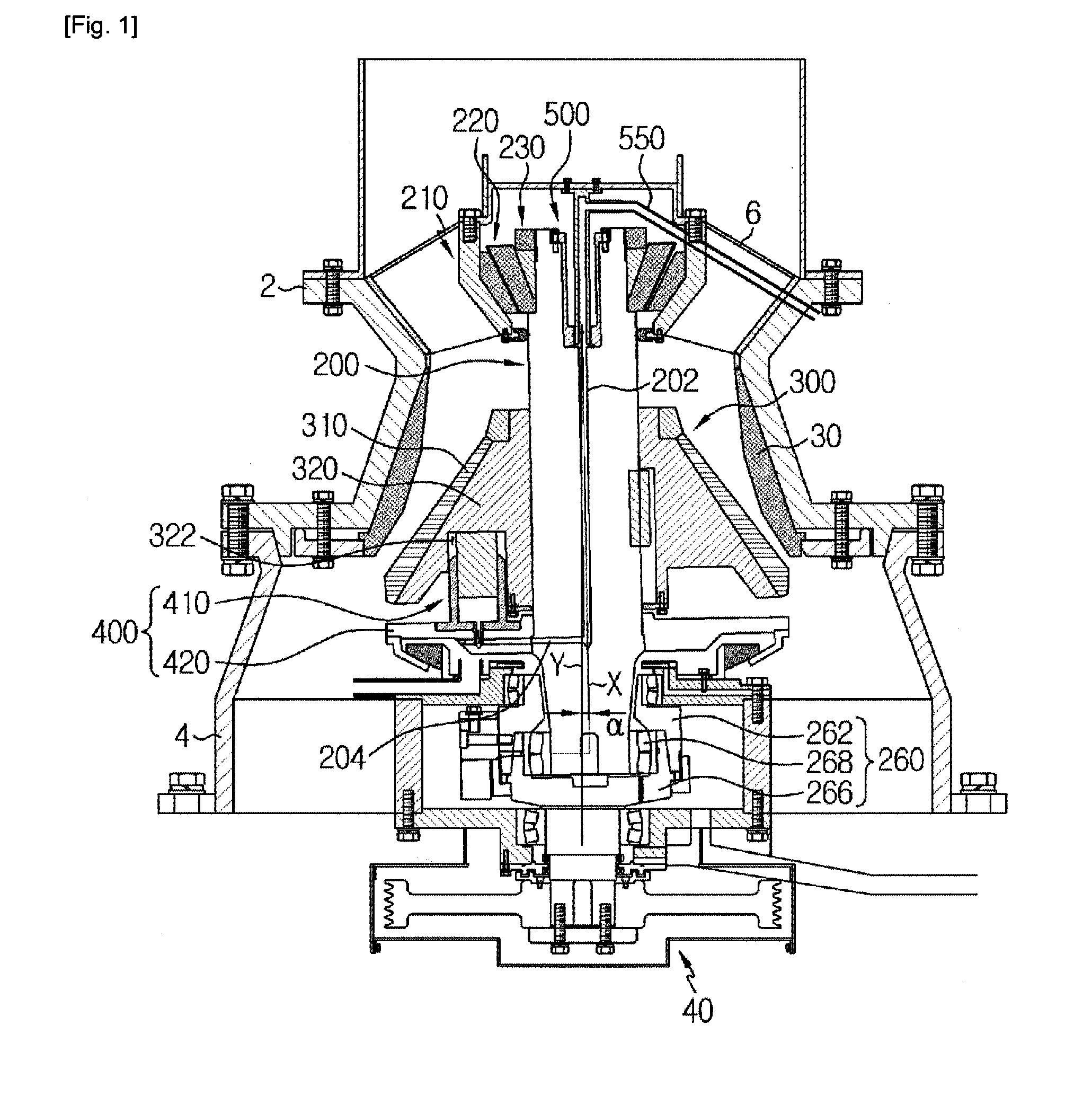
[0032]FIG. 1 is a sectional view illustrating a cone-shaped crusher according to a preferred first embodiment of the invention;
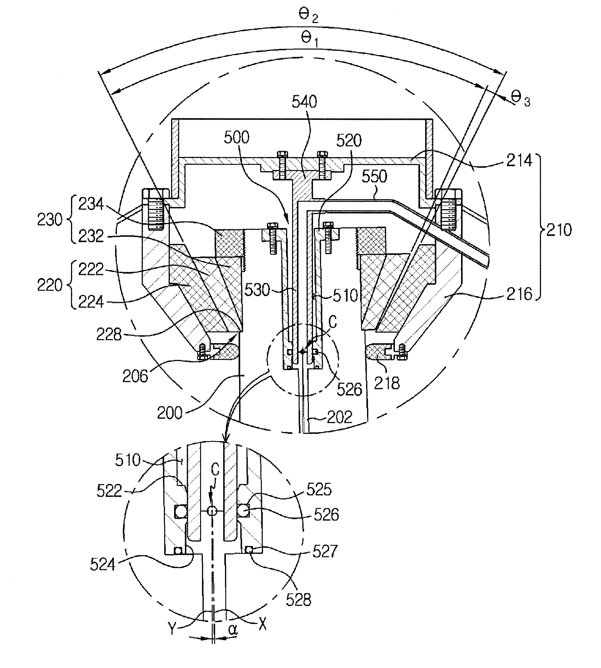
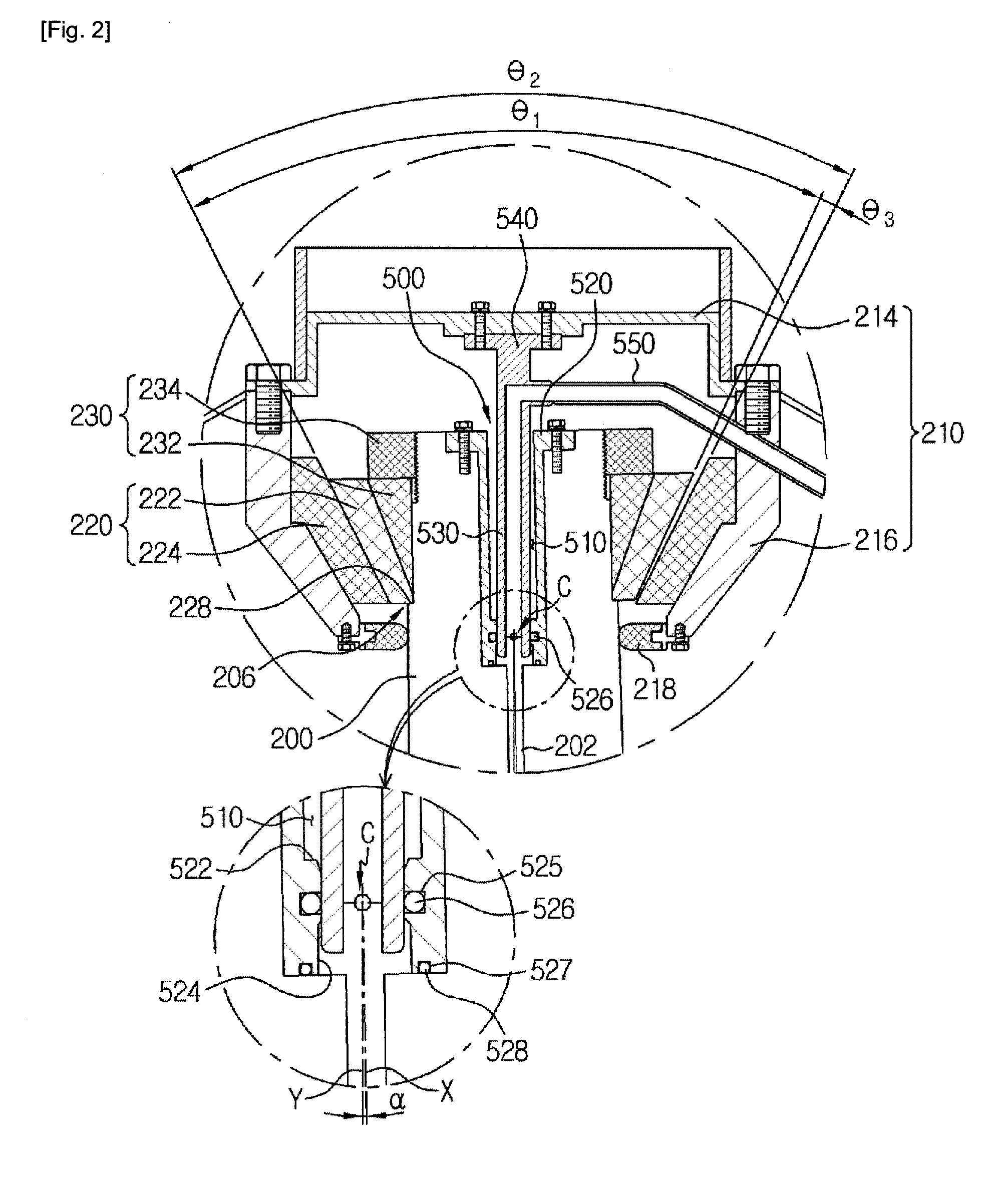
[0033]FIG. 2 is a partially enlarged view illustrating the first embodiment shown in FIG. 1, and illustrating an upper end portion of a main shaft and a suspension bearing chamber;
[0034]FIG. 3 is a partially enlarged view illustrating a cone-shaped crusher according to a second preferred embodiment of the invention, and illustrating the upper end portion of the main shaft and the suspension bearing chamber;
[0035]FIG. 4 is a partially enlarged view illustrating a cone-shaped crusher according to a third preferred embodiment of the invention, and illustrating the upper end portion of the main shaft and the suspension bearing chamber; and.
[0036]FIG. 5 is a partially enlarged view illustrating a cone-shaped crusher according to a fourth preferred embodiment of the invention, and illustrating the upper end portion of the main shaft and the suspension bearing cham...
second embodiment
[0067]FIG. 3 is a partially enlarged view illustrating a cone-shaped crusher according to the invention, and illustrating the upper end portion of the main shaft and the suspension bearing chamber.
[0068]Referring to FIG. 3, the greatest difference between the first embodiment and the second embodiment is the suspension bearing 220. The suspension bearing 220 according to the second embodiment includes a lower support protrusion 226. Also, the configuration of the rotary joint 500 according to the second embodiment is different from the configuration of the rotary joint 500 according to the first embodiment.
[0069]In the second embodiment, the suspension bearing 220 includes the stationary ring 224 provided in the inner circumferential surface of the suspension bearing chamber 210, the rotatable ring 222 coupled to the upper end portion of the main shaft 200 and surrounded by the inner circumferential surface of the stationary ring 224, and the lower support protrusion 226 extending a...
third embodiment
[0089]FIG. 4 is a partially enlarged view illustrating a cone-shaped crusher according to the invention, and illustrating the upper end portion of the main shaft and the suspension bearing chamber.
[0090]Referring to FIG. 4, the difference between the third embodiment and the second embodiment is the structure of the suspension bearing 220. That is, the second embodiment includes the lower support protrusion 226, but the third embodiment includes an upper support protrusion 228 instead of the lower support protrusion 226.
[0091]The upper support protrusion 228 extends annularly from the upper end portion of the rotary ring 222 toward the inner circumferential surface of the suspension bearing chamber 210 and is supported by the upper end portion of the stationary ring 224. Also, a gap is preferably present between an outer circumferential surface of the upper support protrusion 228 and the inner circumferential surface of the suspension bearing chamber 210 so as to prevent wear from o...
PUM
 Abstract
Description
Claims
Application Information