

Production line for afforestation
- Summary
- Abstract
- Description
- Claims
- Application Information
AI Technical Summary
Benefits of technology
Problems solved by technology
Method used
Image

Examples
embodiment 1
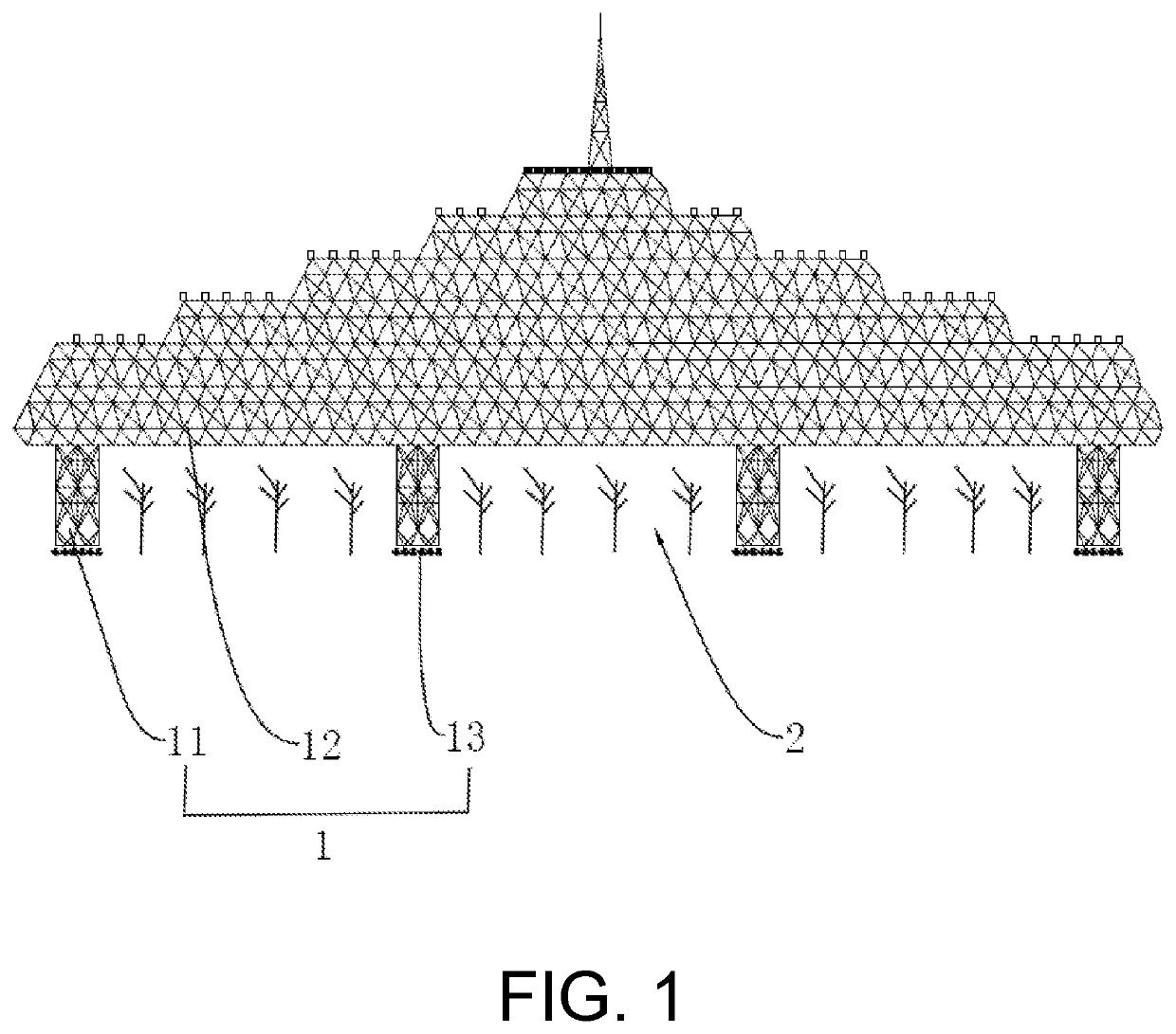
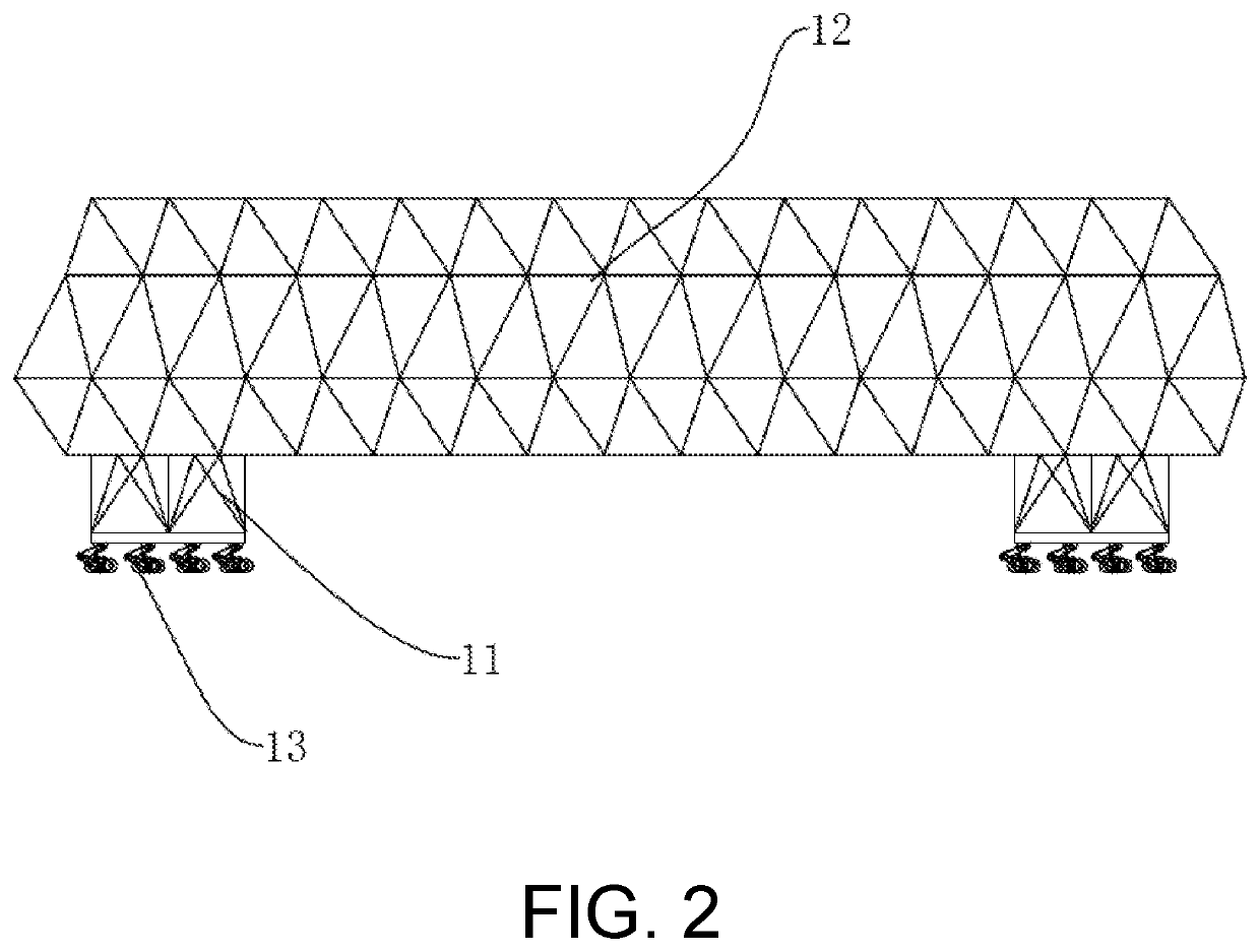
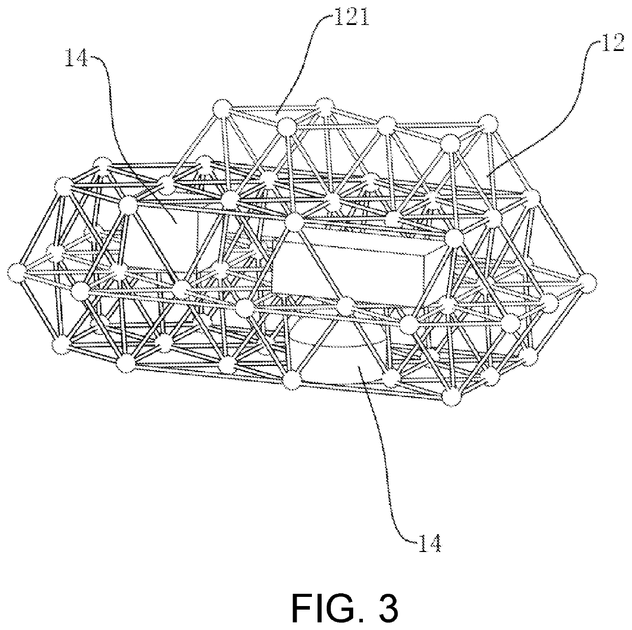
[0044]As shown in FIGS. 1 and 2, a production line for afforestation comprises a mobile platform 1, which has a living area formed thereon, a column 11 disposed at the bottom thereof, and a walking mechanism 13 installed at one end of the column 11 opposite to the other end connected with the mobile platform 1 and moving the mobile platform 1 in the desert. The supporting of the column 11 provides some space between the mobile platform 1 and the ground, so that the space under the mobile platform 1 can be used for the operation of an equipment such as a tree planting machine. During the daytime, the sheltering of the mobile platform 1 forms a sunshade zone 2 for cultivating seedlings therein, so as to shelter the newly planted seedlings from the sunlight in the desert, making the newly planted seedlings less likely to die. Furthermore, the people can live in the living area, so that they can work in the desert for a long time.
[0045]The mobile platform 1 comprises a mobile village, w...
embodiment 2
[0050]Referring to FIGS. 10 and 11, the walking mechanism 13 comprises a flat car, the flat car comprises a flat car platform 133 and a walking wheel system 131 installed at the bottom of the flat car platform 133. The walking wheel system 131 comprises a plurality of evenly arranged walking wheel sets, each of which can adopt the structure of an aircraft landing gear.
[0051]Preferably, for the purpose of better walking in the desert, the adjacent supporting wheels 1313 of the walking wheel sets are equipped with a caterpillar track 1314, so as to prevent the walking wheel sets from being trapped in the sands.
[0052]In particular, one embodiment of the walking wheel sets comprises a shock-absorbing support arm, a mounting frame 1316, a support wheel 1313 rotatably connected to the mounting frame 1316, a walking motor driving the support wheel 1313 to rotate, and a battery supplying power for the walking motor. The battery can be powered by solar energy. The shock-absorbing support arm...
embodiment 3
[0054]Referring to FIG. 12, an anti-wind ground pile 3 is installed at the bottom of the flat car platform 133, which is driven downward by hydraulic cylinder 42 so as to be driven into the sand, achieving fixing effect against the wind.
PUM
 Abstract
Description
Claims
Application Information