

Tight fastening type size-free container carrying bag
- Summary
- Abstract
- Description
- Claims
- Application Information
AI Technical Summary
Benefits of technology
Problems solved by technology
Method used
Image

Examples
example 1
Arrangement Example 1
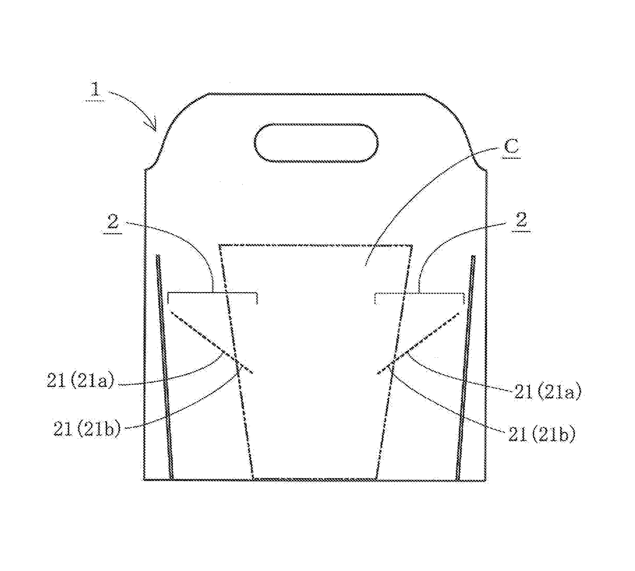
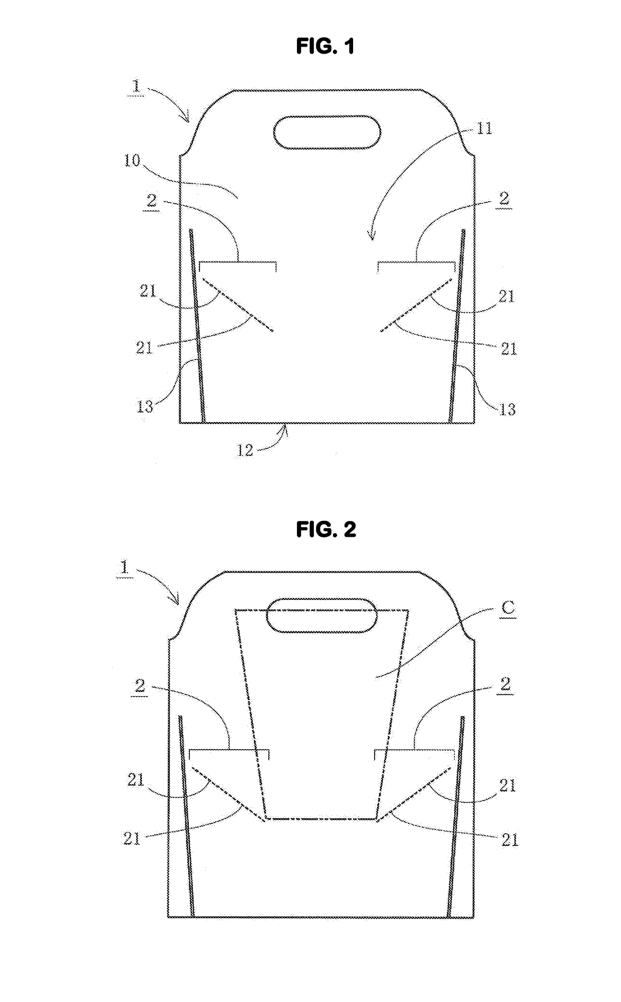
[0041]In this arrangement example, a container insertion portion is formed at a center of the container holding portion of the bag body 1, and the holding zone 2 is substantially symmetrically provided on each of right and left sides of this container insertion portion (see FIG. 1). The spot joining portions 21, 21, . . . in the holding zone 2 are arranged to be linearly provided from an outer and upper side toward an inner and lower side, and the spot joining portion 21 and a gap having substantially the same size as a size of the spot joining portion 21 are alternately provided.
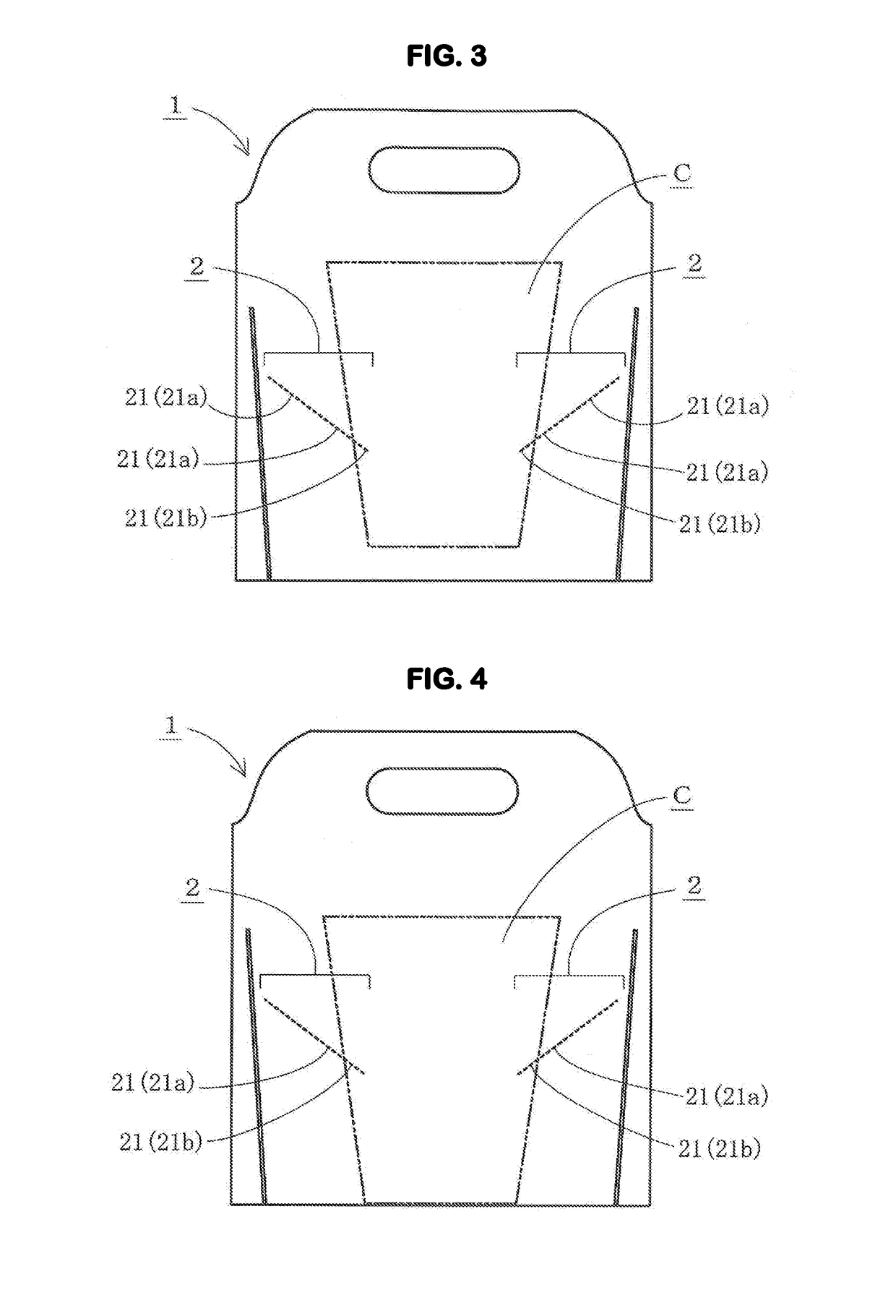
[0042]In addition, when the container C (two-dot chain line in the figure) is inserted from the opening 11 as illustrated in FIG. 2, a main body of the container C is pressed against at least a portion of the spot joining portion 21 in the holding zone 2 as illustrated in FIG. 3, and thus the spot joining portion 21 corresponding to this pressed part may be peeled off.
[0043]Thereafter, ...
example 2
Arrangement Example 2
[0049]According to an arrangement example illustrated in FIG. 6, two straight rows of , in which the spot joining portions 21, 21, . . . in the holding zone 2 are arranged to be linearly provided from an outer and upper side toward an inner and lower side, and the spot joining portion 21 and a gap having substantially the same size as a size of the spot joining portion 21 are alternately provided, are provided in parallel on each of right and left sides, thereby configuring the holding zone 2. In this way, support strength of the container may be improved.
example 3
Arrangement Example 3
[0050]According to an arrangement example illustrated in FIG. 7 and FIG. 8, the spot joining portions 21, 21, . . . in the holding zone 2 are arranged to be curvedly provided from an outer and upper side toward an inner and lower side, the spot joining portion 21 and a gap are alternately provided, and a size (length) of the spot joining portion 21 may be adjusted according to support strength of the container C.
PUM
 Abstract
Description
Claims
Application Information