Precision table

a precision table and precision technology, applied in the direction of toothed gearings, mechanical equipment, belts/chains/gearrings, etc., can solve the problems of reducing precision, vibration, and the relationship between nut and screw also presents problems, and achieves high accuracy, reliable and simple maintenance, and easy manufacturing of parts.

Inactive Publication Date: 2006-07-20
LAS NAVAS GARCIA JOSE MARIA
View PDF24 Cites 16 Cited by
  • Summary
  • Abstract
  • Description
  • Claims
  • Application Information

AI Technical Summary

Benefits of technology

[0003] The prime object of the present invention is therefore to provide a linear translation device which is highly accurate but which is composed of easily manufactured parts, reliable and simple to maintain, an

Problems solved by technology

The relationship between nut and screw also presents problems.
If the nut fits the screw too tightly rotation is impeded and vibration tends to occur.
If the nut fits too loosely

Method used


Image

  • Precision table
  • Precision table
  • Precision table

Examples


Embodiment Construction

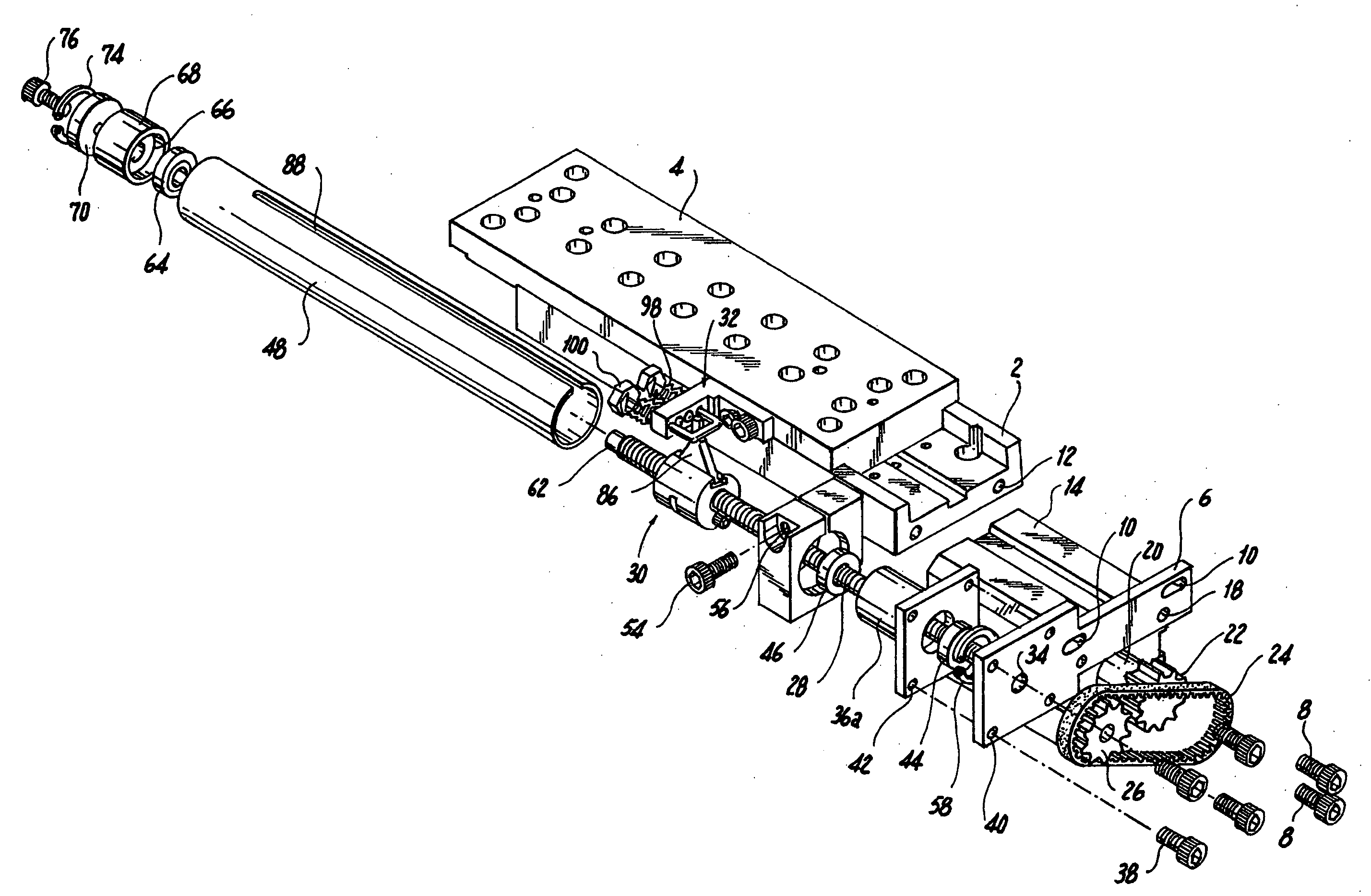
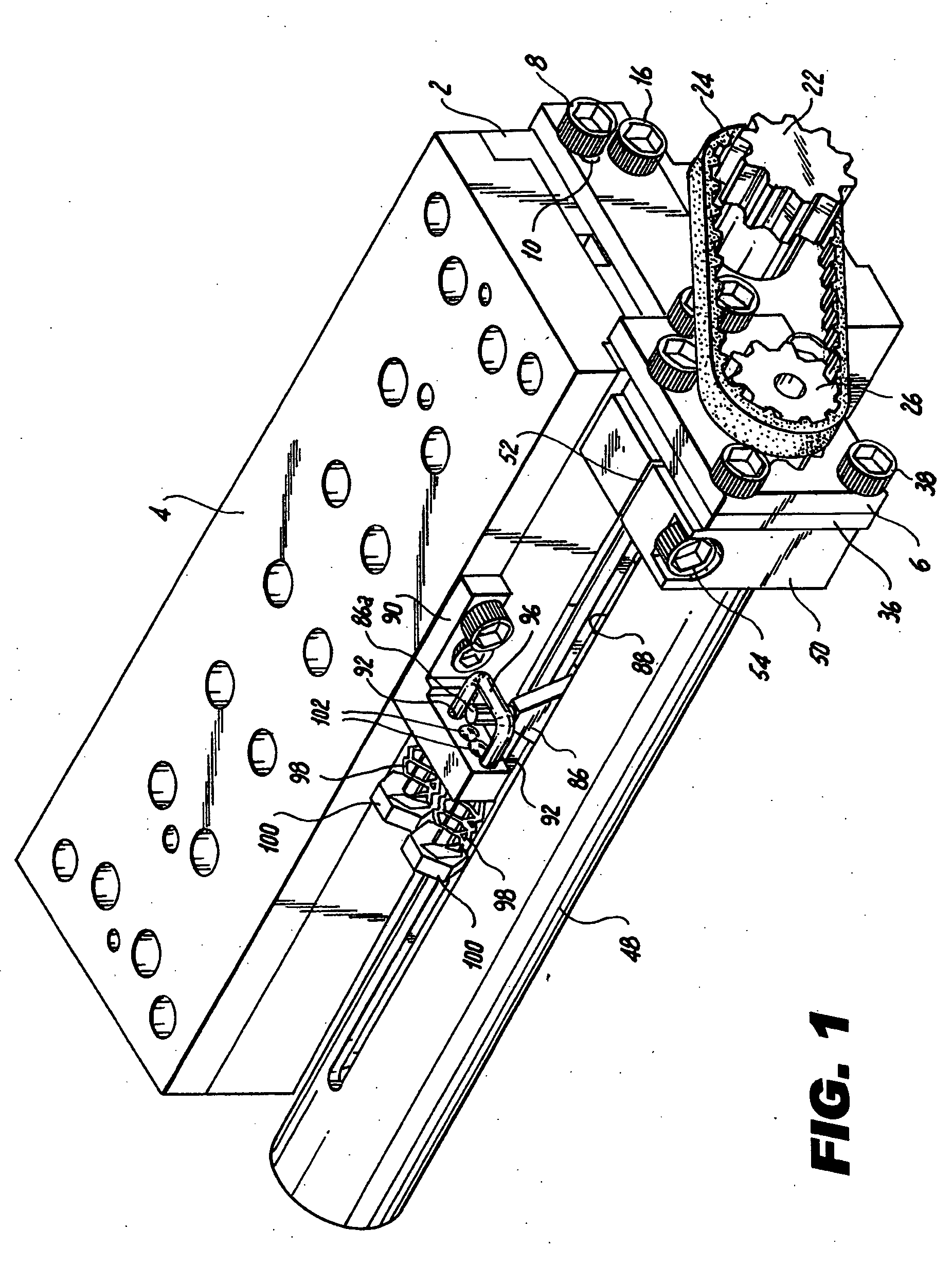
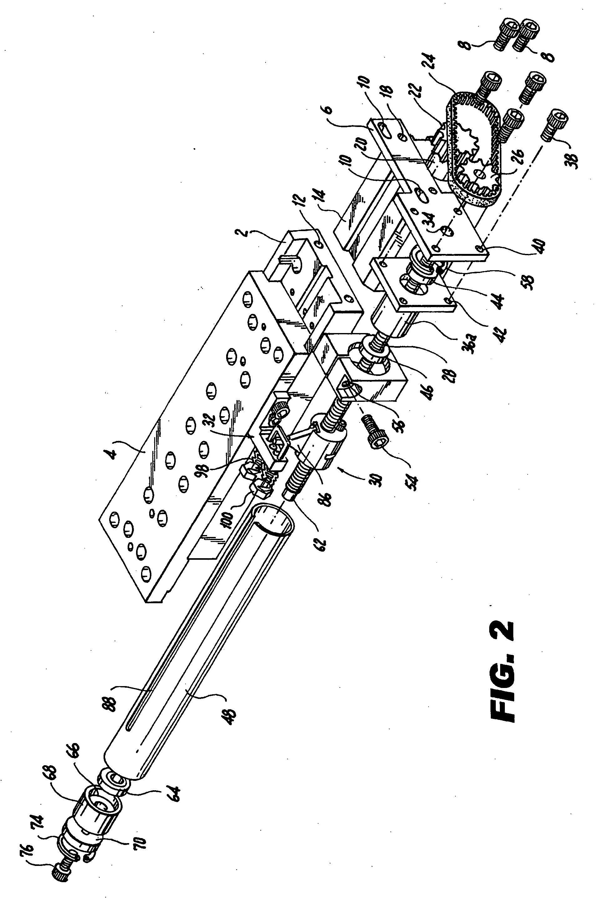
[0014] A typical table comprises a fixed part generally designated 2 and a moveable part generally designated 4 slideable thereover, the engaging surfaces of those tables being cooperatingly shaped and machined so that the table 4, as it is moved, slides smoothly and accurately over the fixed part or base 2. The means for accurately moving the table 4 over the fixed part 2, a preferred embodiment of which is here specifically disclosed, comprises a support plate 6 secured to the base 2 by screws 8 passing through holes 10 in the support plate 6 and being received in holes 12 in the table base 2. All of the operative parts of the table moving means are mounted on that support plate 6.

[0015] In the embodiment here specifically disclosed the table part 4 is designed to be moved by means of a motor 14 secured to the support plate 6 by screws 16 passing through holes 18 in the support plate 6 and engaging the motor 14. The motor has an output shaft 20 with a driving part 22, such as a g...


PUM


Abstract

Precision movement of a table part by movement of a nut over a lead screw is achieved by a less rigorously precise structure than has heretofore been thought necessary. To that end the screw is fixedly supported only at one end and is rotatable in bearings mounted within a rigidly mounted tube which at least partially surrounds the screw, play in those bearings is minimized by exerting axial pressure thereon, the nut is especially designed to engage the screw only at separated points, thereby to reduce friction and play in the nut, and the nut is connected to the moveable table part by structure passing through an opening in the tube and resiliently engaging the moveable table part to compensate for displacement and play.

Description

FIELD OF THE INVENTION [0001] The invention relates to a mechanical precision device such as a precision table that can be useful in a variety of linear movement applications. BACKGROUND OF THE INVENTION [0002] A wide variety of linear translation devices are known, most of them involving a table slideable over a supporting part and moved by rotation of an externally threaded shaft on which an internally threaded nut is mounted for movement along the axis of the shaft. The shaft is driven either directly or indirectly by a motor or other appropriate drive mechanism. A typical mechanical arrangement involves fixedly supporting the shaft at two spaced points precisely rigidly mounted independently of the moveable part, and also providing very precise machined surfaces on the table and on the supporting part over which the table is slideable, precise alignment of the shaft with the direction of movement of the table being necessary to avoid jamming or stiff resistance to shaft rotation...

Claims


Application Information

Patent Timeline
IPC IPC(8): F16H25/20
CPCF16H25/2006F16H25/24Y10T74/1868Y10T74/18576Y10T74/18656F16H2025/2445
Inventor LAS NAVAS GARCIA, JOSE MARIA
Owner LAS NAVAS GARCIA JOSE MARIA
Why Eureka
Try Eureka