Spherical contact type friction characteristic testing device under ultrasonic vibration
A technology of spherical contact and friction characteristics, applied in the direction of measuring devices, testing wear resistance, using mechanical devices, etc., can solve problems such as inability to study friction and wear characteristics, and achieve a high degree of automation
- Summary
- Abstract
- Description
- Claims
- Application Information
AI Technical Summary
Problems solved by technology
Method used
Image
Examples
no. 1 example
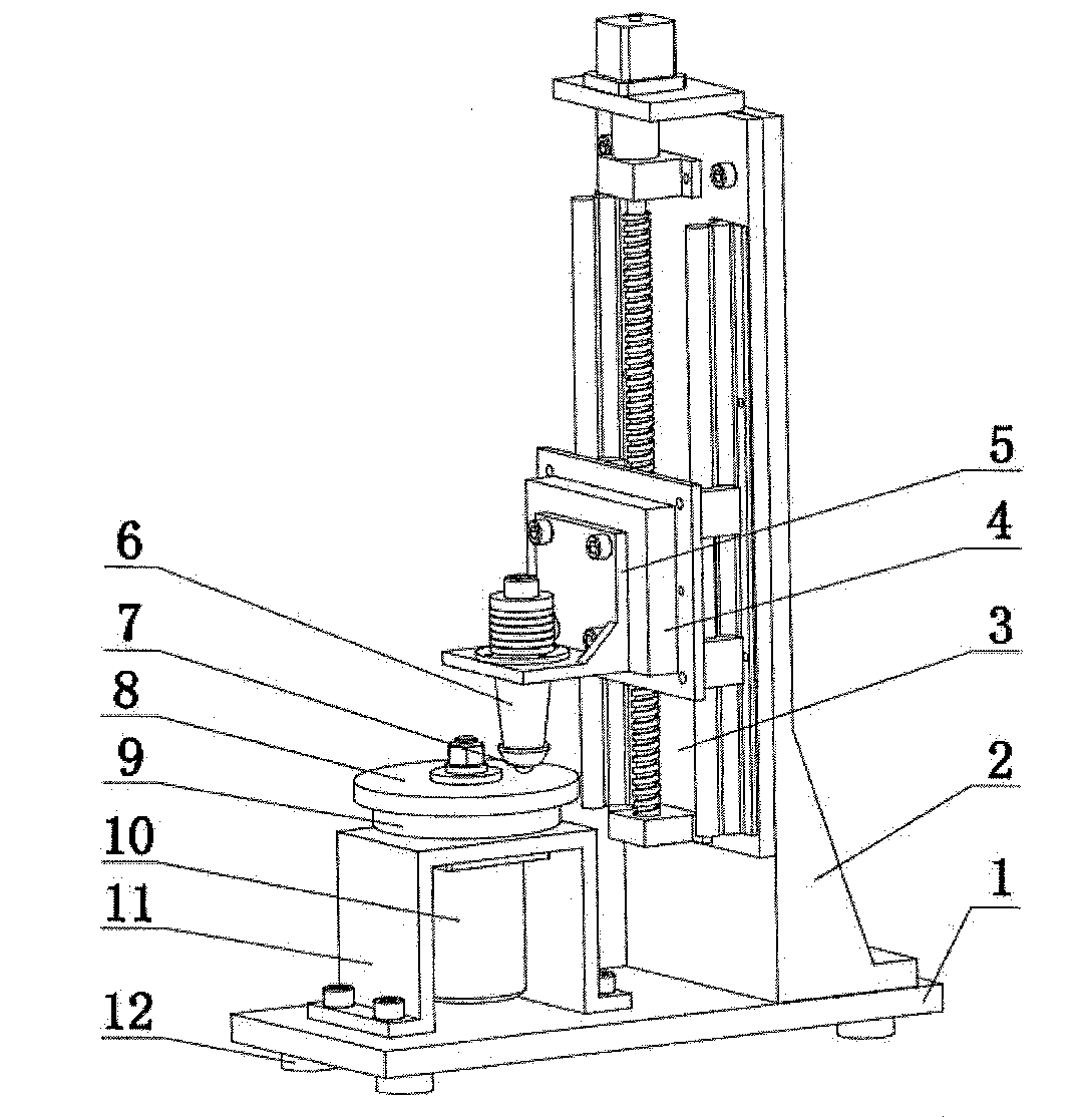
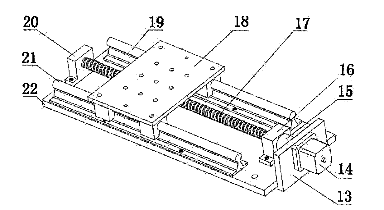
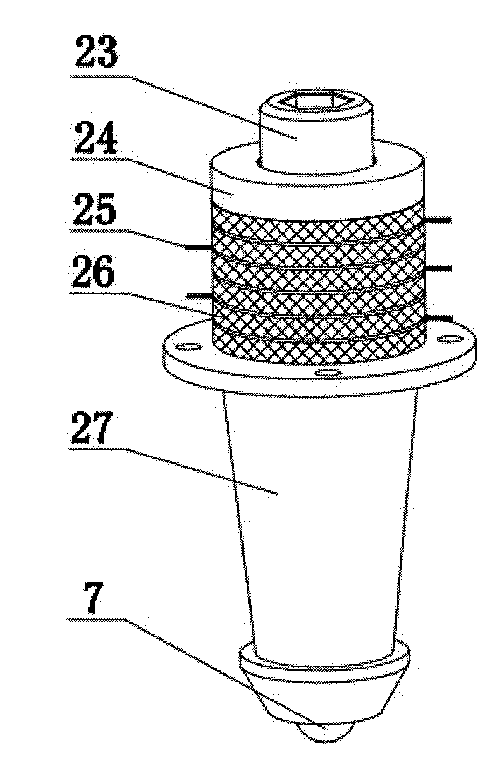
[0026] Refer to Figure 1 to Figure 5 As shown, this embodiment is composed of a main movement unit, a loading unit and a force measuring unit;
[0027] The main motion unit includes a base 1, a DC motor bracket 11, a DC motor 10, and a lower sample mounting table 9. The bottom surface of the base 1 is equipped with four cylindrical shock-absorbing rubbers 12 with the same structure. The DC motor bracket 11 uses The bolts are fixed on the base 1, the DC motor 10 is fixedly installed on the DC motor support 11 through the through holes on the flange surface, and the lower sample mounting table 9 is connected with the output shaft of the DC motor. Refer to Figure 5 As shown, the lower sample mounting table 9 is composed of a rotating table 29, a pressure block 30, a spring washer 31, and a nut 32. The bottom end of the rotating table 29 is provided with a hole and a keyway, and the output shaft of the DC motor 10 is connected through the hole and the keyway. Connect, and screw in...
no. 2 example
[0035] Refer to Image 6 versus Figure 7 As shown, the structure of the second embodiment is basically the same as that of the first embodiment. The difference is that the piezoelectric ultrasonic transducer holder 5 connected to the three-axis force sensor 4 is a straight-plate structure, and the piezoelectric ultrasonic transducer 6 Mounted horizontally on the piezoelectric ultrasonic transducer holder 5, the upper sample 8 is mounted on the front of the piezoelectric ultrasonic transducer 6, and the front of the front cover 27 of the piezoelectric ultrasonic transducer 6 is milled into a flat structure up and down. , The lower flat surface is machined with an inner cone with a Morse taper, which is in interference fit with the outer cone on the rear end of the upper sample 7, that is, the axis of the upper sample 7 is perpendicular to the axis of the piezoelectric ultrasonic transducer 6. When the piezoelectric ultrasonic transducer 6 is connected to an ultrasonic power sour...
PUM
 Abstract
Description
Claims
Application Information
 - R&D
- Intellectual Property
- Life Sciences
- Materials
- Tech Scout
- Unparalleled Data Quality
- Higher Quality Content
- 60% Fewer Hallucinations
Browse by: Latest US Patents, China's latest patents, Technical Efficacy Thesaurus, Application Domain, Technology Topic, Popular Technical Reports.
© 2025 PatSnap. All rights reserved.Legal|Privacy policy|Modern Slavery Act Transparency Statement|Sitemap|About US| Contact US: help@patsnap.com


