Spherical contact friction characteristic testing device under ultrasonic vibration

A technology of spherical contact and friction characteristics, which is used in measuring devices, testing wear resistance, and using mechanical devices. It can solve problems such as inability to study friction and wear characteristics, and achieve a high degree of automation.

Inactive Publication Date: 2016-04-13
JILIN UNIV
View PDF6 Cites 0 Cited by
  • Summary
  • Abstract
  • Description
  • Claims
  • Application Information

AI Technical Summary

Problems solved by technology

However, none of the existing friction and wear testing machines can conduct friction and wear characteristics research under ultrasonic vibration

Method used


Image

  • Spherical contact friction characteristic testing device under ultrasonic vibration
  • Spherical contact friction characteristic testing device under ultrasonic vibration
  • Spherical contact friction characteristic testing device under ultrasonic vibration

Examples


no. 1 example

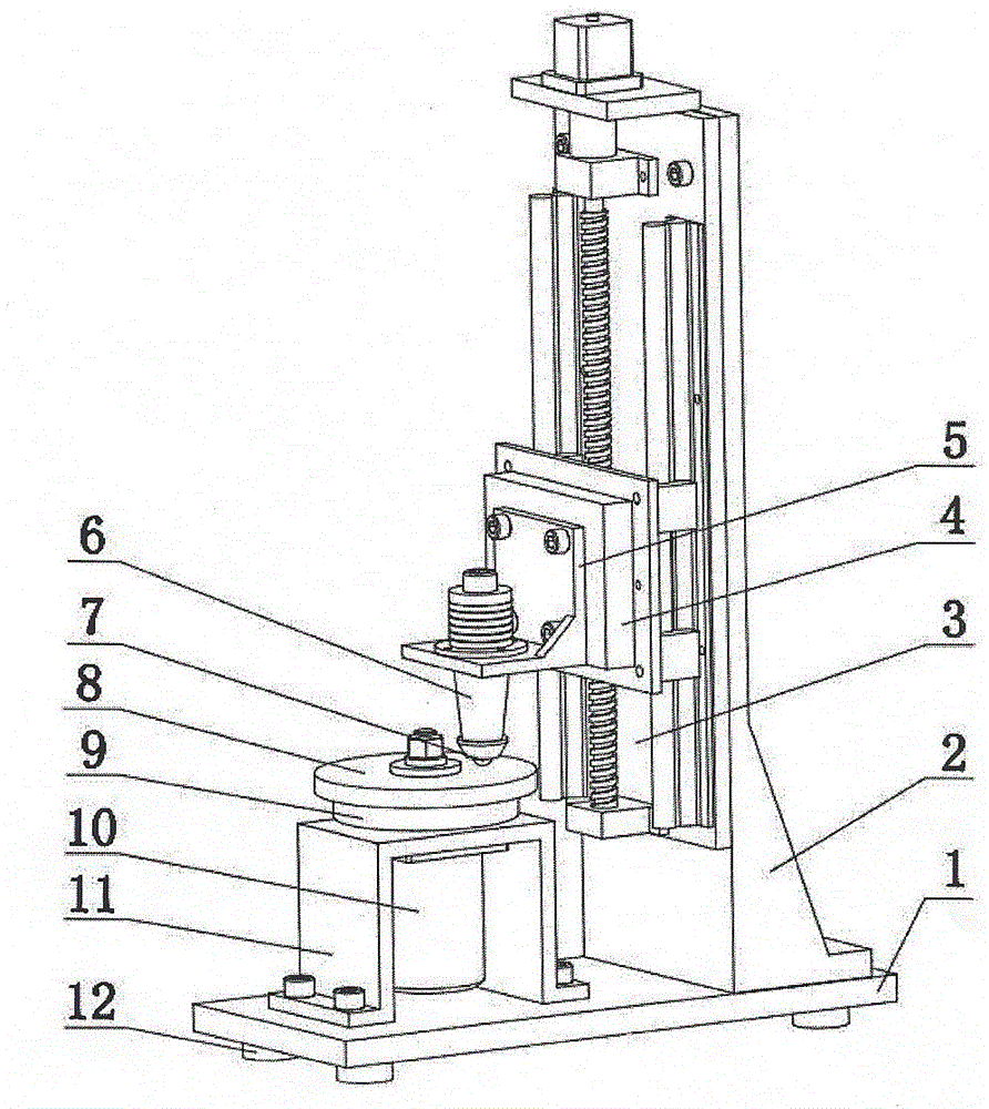
[0026] refer to Figure 1 to Figure 5 As shown, the present embodiment is made up of main motion unit, loading unit and force measuring unit;

[0027] The main motion unit includes a base 1, a DC motor support 11, a DC motor 10, and a lower sample mounting table 9. Four cylindrical shock-absorbing rubbers 12 with the same structure are installed on the bottom surface of the base 1. The DC motor support 11 adopts The bolts are fixed on the base 1, the DC motor 10 is fixedly installed on the DC motor support 11 through the through hole on the flange surface, and the lower sample mounting table 9 is connected with the output shaft of the DC motor. refer to Figure 5 As shown, the lower sample mounting table 9 is composed of a rotary table 29, a pressing block 30, a spring washer 31, and a nut 32. The bottom end surface of the rotary table 29 is provided with a hole and a keyway, and the output shaft of the DC motor 10 is connected through the hole and the keyway. connected, and...

no. 2 example

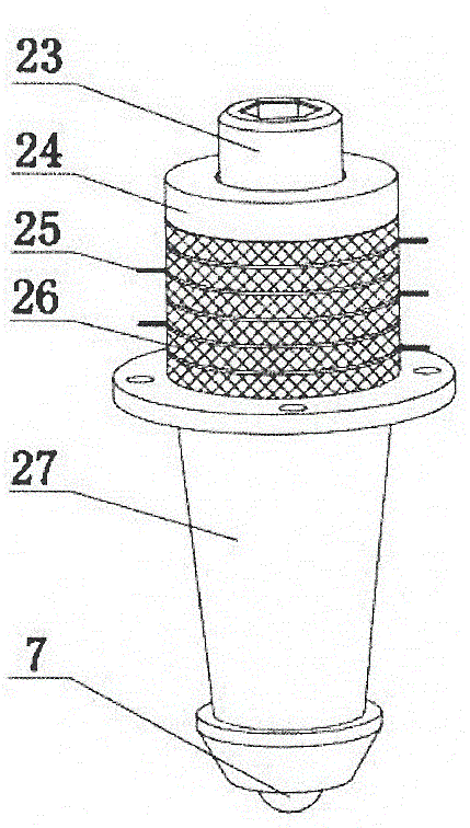
[0035] refer to Figure 6 and Figure 7 As shown, the structure of the second embodiment is basically the same as that of the first embodiment, except that the piezoelectric ultrasonic transducer fixing bracket 5 connected to the triaxial force sensor 4 is a straight plate structure, and the piezoelectric ultrasonic transducer 6 Installed horizontally on the fixed frame 5 of the piezoelectric ultrasonic transducer, the upper sample 8 is installed on the front part of the piezoelectric ultrasonic transducer 6, and the front part of the front cover plate 27 of the piezoelectric ultrasonic transducer 6 is milled into a flat structure up and down , the lower flat surface is processed with an inner cone with a Morse taper, which is interference fit with the outer cone on the rear end surface of the upper sample 7, that is, the axis of the upper sample 7 is perpendicular to the axis of the piezoelectric ultrasonic transducer 6. When the piezoelectric ultrasonic transducer 6 is conn...


PUM


Abstract

The invention discloses a spherical contact type friction characteristic testing device under ultrasonic vibration. The device consists of a main movement unit, a loading unit and a dynamometer unit, wherein the torque output by a step motor is converted into axial pressure of a sliding table through a lead screw nut pair of a trapezoidal screw, and an upper sample and a lower sample which are arranged at the bottom of a piezoelectric micromachined ultrasonic transducer are contacted with each other, and certain pressure is applied to the lower sample; when the piezoelectric micromachined ultrasonic transducer is connected with an ultrasonic power supply, the upper sample produces ultrasonic frequency vibration with micron-grade amplitude in the horizontal direction or the vertical direction, the lower sample rotates together with a rotating platform and forms a friction pair with the upper sample, so that the friction characteristic of the spherical contact under ultrasonic vibration can be tested. The device can be used for accurately controlling the testing parameters, is high in degree of automation, and can be used for performing spherical contact friction experiments of various types of friction materials under different ultrasonic vibration frequencies and vibration amplitudes.

Description

technical field [0001] The invention relates to a friction and wear testing machine, in particular to a spherical surface contact friction characteristic testing device under ultrasonic vibration. Background technique [0002] The friction force between objects is affected by many factors, such as: the roughness of the friction surface, sliding speed, properties of materials, normal force, stick-slip characteristics, ambient temperature and relative humidity, lubrication and vibration, etc. Among them, the method of using vibrations with different frequencies and amplitudes to affect friction has been widely used in many fields. As early as 1959, American scholar Fridman et al. studied the influence of vertical vibration on the coefficient of static friction. It was found that as the amplitude increased, the static friction coefficient gradually decreased until it dropped to zero, and finally a negative value appeared. Later, Godfrey used the designed experimental device t...

Claims


Application Information

Patent Timeline
Patent Type & Authority Patents(China)
IPC IPC(8): G01N3/56G01N19/02
Inventor 董景石王良亮傅成杰王成川薛江鹏狄雷方盛洲蔡浩
Owner JILIN UNIV
Why Eureka
Try Eureka