Self-Retaining Recirculating Ball-Worm and Gear Device

a self-retaining, gear-based technology, applied in the direction of toothed gearings, belts/chains/gearrings, gearings, etc., can solve the problems of inefficient power conversion, especially problematic in such mechanisms, and the mechanism to suffer from premature wear

Inactive Publication Date: 2006-07-20
TONG DAVY
View PDF5 Cites 38 Cited by
  • Summary
  • Abstract
  • Description
  • Claims
  • Application Information

AI Technical Summary

Problems solved by technology

The sliding friction causes the mechanism to suffer from premature wear and inefficient power conversion.
Backlash has also been especially problematic in such mechanisms.
The introduction of balls has caused the assembly process of ball-worm transmissions to be cumbersome or awkward.
Because balls tend to scatter when unconstrained, ball installation during assembly is difficult.
The awkward assembly process also causes replacement of worn-out balls and other parts to be likewise burdensome.
Consequently, the ball-worm transmission is more costly to manufacture and maintain.
Subsequently, the ball-worm transmission is more complex than its classical predecessor, which needed no such ball-retaining mechanism.
The ball-retainer also...

Method used


Image

  • Self-Retaining Recirculating Ball-Worm and Gear Device
  • Self-Retaining Recirculating Ball-Worm and Gear Device
  • Self-Retaining Recirculating Ball-Worm and Gear Device

Examples


Embodiment Construction

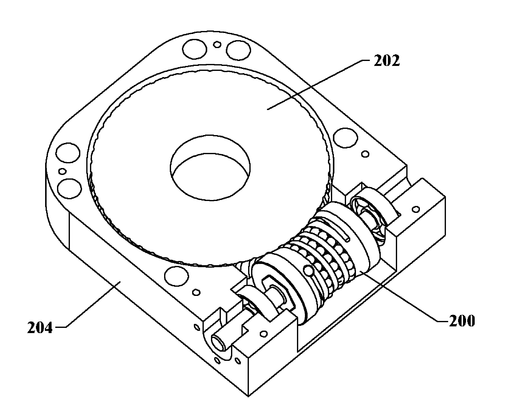
[0073]FIGS. 4A to 4C present several overall views of the self-retaining recirculating ball-worm and gear device. The device comprises a self-retaining ball-worm 200, gear 202, and housing 204. Housing 204 is designed to enclose and axially support the internal components of ball-worm 200 and gear 202. Bearings, bushings, or other support mechanisms may be included in housing 204 to axially support and restrict ball-worm 200 and gear 202 to their respective axes of rotation.

[0074]FIGS. 5A to 5C and FIG. 6 show several views of the device with housing 204 omitted. The axis of ball-worm 200 and axis of gear 202 are orthogonal but non-intersecting. The ball-worm comprises a worm shaft 220, worm collar 222, plug 226, and plurality of balls 224. The gear has a plurality of gear grooves 240 separated at periodic angular intervals which are designed to engage the balls 224 of the ball-worm. Worm shaft 220 and worm collar 222 are rigidly fastened together so that rotation of one causes the...


PUM


Abstract

A self-retaining ball-worm and gear mechanism is provided to facilitate the rotational transmission of motion between two orthogonal but non-intersecting axes. A circuit of balls introduced as rolling elements indirectly couples the worm and gear, and eliminates the sliding friction characteristic of classical worm and gear mechanisms. The mechanism comprises a ball-worm (200), gear (202), and axial supports or housing (204). The ball-worm defines the ball circulation path. The worm helix is designed to retaining the balls such that no additional ball-retaining components are necessary. Magnetism may optionally or additionally be employed to attract the metal balls to the worm body, further enhancing ball self-retention. The gear comprises a plurality of grooves designed to engage the helix of balls on the worm. The path of the worm helix is mathematically accurate so that balls simultaneously engage multiple gear grooves, increasing the torque load capabilities of the device.

Description

BACKGROUND OF THE INVENTION [0001] 1. Field of Invention [0002] The present invention relates to mechanical rotational-to-rotational transmissions, specifically to worm and gear transmissions. [0003] 2. Prior Art [0004] The classical worm and gear mechanism represented in FIG. 1 is commonly used for speed reduction, rotational positioning, motion control, and other rotational-to-rotational transmission applications. The classic mechanism consists of a worm 100, gear 102, and axial support components (not shown) such as bearings or bushings. Sliding motion between the helix of worm 100 and teeth of gear 102 cause the gear to rotate as the worm is rotated. The sliding friction causes the mechanism to suffer from premature wear and inefficient power conversion. Backlash has also been especially problematic in such mechanisms. Several approaches that utilize dual gearing and anti-backlash springs only eliminates the backlash for a narrow torque range. The motion of the mechanism is also...

Claims


Application Information

Patent Timeline
IPC IPC(8): F16H1/16
CPCY10T74/19828F16H1/163
Inventor TONG, DAVY
Owner TONG DAVY
Why Eureka
Try Eureka