

Imprinting machine and device manufacturing method
a technology of printing machine and manufacturing method, which is applied in the field of printing machine, can solve the problems of unfavorable product quality control, damage to parts of the mold, and difficulty in precisely pressing such a mold against the object,
- Summary
- Abstract
- Description
- Claims
- Application Information
AI Technical Summary
Benefits of technology
Problems solved by technology
Method used
Image

Examples
first embodiment
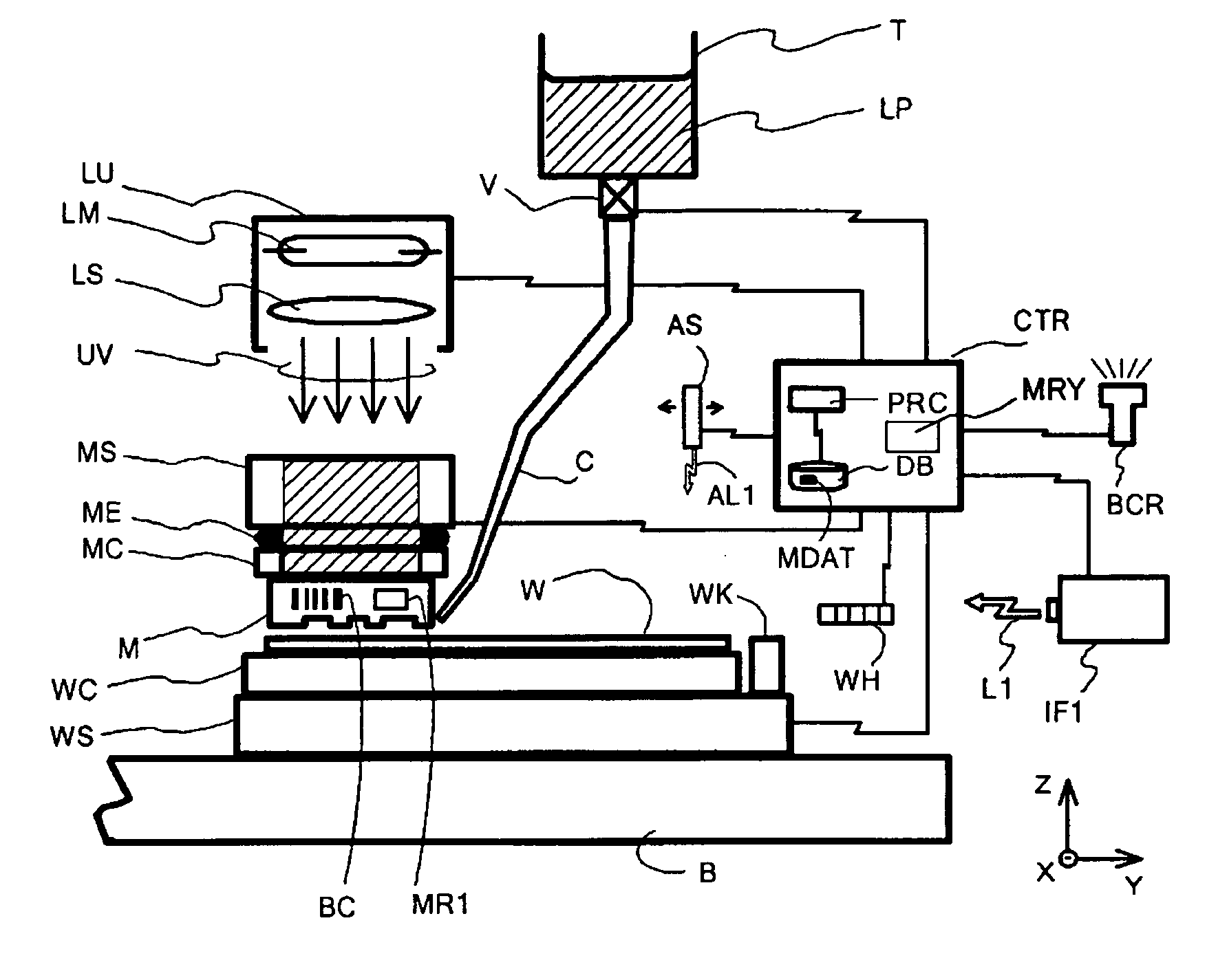
[0030]FIG. 1 shows a structure of a nanoimprint apparatus (imprinting machine) according to a first embodiment of the present invention.
[0031] In FIG. 1, M denotes a mold having a fine concave-convex pattern on its bottom surface, and is held on a bottom of a mold chuck MC by a vacuum absorption or another method.
[0032] A mold stage MS is supported by a frame (not shown) of an apparatus body, and rotatable in XYZ-axes directions and rotational directions around these axes.
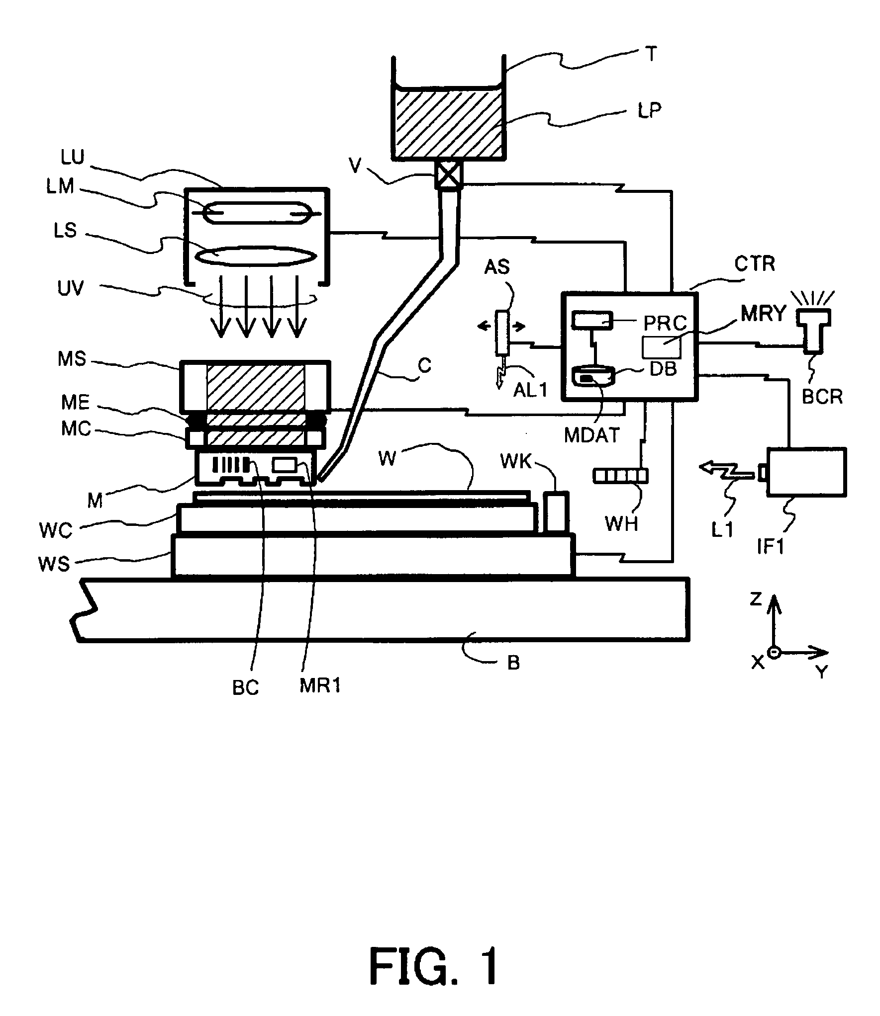
[0033] The mold stage MS and the mold chuck MC are connected to each other via a low elastic joint ME made of an elastic member. The low elastic joint ME acts as a spring member of a fine stroke, and elastically absorbs displacements and deformations. When the mold M end-contacts the wafer W, the low elastic joint ME deforms and alleviates the uneven pressure applied to the mold M.
[0034] The necessary stroke for the low elastic joint ME is so small that control over a shape, like a coil spring and a flat spring...
second embodiment
[0122] While the first embodiment describes the nanoimprint apparatus that uses, as a second measuring means, an interferometer and a mirror provided in the mold M, this embodiment describes a nanoimprint apparatus that uses, as a second measuring means, a component other than the interferometer, with reference to FIGS. 5A to 5C.
[0123]FIGS. 5A to 5C show a pattern transferring procedure similar to that shown in FIGS. 4AA to 4BF in the first embodiment, but are different from the first embodiment in that there is no interferometer and the mold M has no mirror.
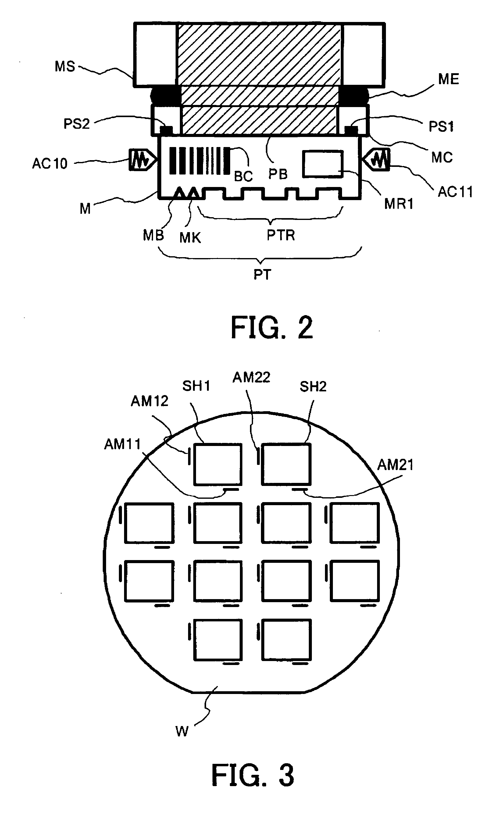
[0124] In FIGS. 5A to 5C, the mold alignment mark MK and the wafer alignment mark AM 12 are made of a diffraction grating similar to the first embodiment. However, the alignment measurement is designed to be most precise when both alignment marks MK and AM12 are adhered to each other, or when the mold M is pressed against the wafer W.
[0125]FIG. 7A shows a relationship of this embodiment between the alignment measurement error...
third embodiment
[0135]FIGS. 6A to 6C show a pattern transferring procedure in a nanoimprint apparatus according to a third embodiment of the present invention, which is similar to that shown in FIGS. 5A to 5C in the second embodiment, but is different from the second embodiment in that an alignment mark is added to each of the mold M and the wafer W.
[0136] In FIGS. 6A to 6C, the mold alignment marks MK1 and MK2 and the wafer alignment mark AM13 and AM14 are made of a diffraction grating similar to the first and second embodiments. However, the alignment measurement is designed to be most precise when the mold alignment mark MK1 and the corresponding wafer alignment mark AM13 are spaced from each other by the first distance h1, and the mold alignment mark MK2 and the corresponding wafer alignment mark AM14 are adhered to each other or spaced from each other by the distance h2. FIGS. 7B and 7C show this state.
[0137]FIG. 7B shows a relationship between the alignment measurement error of a combinatio...
PUM
| Property | Measurement | Unit |
|---|---|---|
| Distance | aaaaa | aaaaa |
| Elasticity | aaaaa | aaaaa |
Abstract
Description
Claims
Application Information