Eddy-current probe

a technology of eddy current and probe, which is applied in the direction of magnetic property measurement, material magnetic variables, instruments, etc., can solve the problems of affecting the accuracy of the test results, the substrate is likely to be damaged by application, and the sticktion occurs more frequently, so as to reduce the probability of sticktion, the durability and lifetime performance is high, and the test results are high

Inactive Publication Date: 2006-07-20
TDK CORPARATION
View PDF2 Cites 24 Cited by
  • Summary
  • Abstract
  • Description
  • Claims
  • Application Information

AI Technical Summary

Benefits of technology

[0013] It is therefore an object of the present invention to provide an eddy-current probe for high resolution testing, possessing very high performances of the durability and lifetime by reducing an occurrence probability of the sticktion.
[0015] Because the first surface of the substrate facing to the subject (the measurement surface) has a non-planar form having the at least one convex-surface portion and therefore has a small facing / contact area with the subject's surface, the sticktion hardly occurs. Even if the sticktion occurs, much less external-force application should be needed to remove the probe from the subject's surface against the sticktion. Consequently, a damage probability by the sticktion is drastically reduced, and therefore, the durability and lifetime can be improved in a large extent. Further, because the at least one eddy-current sensor is formed on the at least one concave-surface portion formed on the second surface (the opposite surface to the measurement surface), which is corresponding to the at least one convex-surface portion, the distance between the subject's surface and the eddy-current sensor does not increase, and therefore, a high performance of resolution is provided.
[0021] Preferably, a lubricant layer, a diamond-like carbon (DLC) layer, or both of a DLC layer and a lubricant layer are formed on the first surface having a plurality of concaves and convexes. The lubricant layer, the DLC layer, or both of the DLC layer and the lubricant layer formed on the surface can prevent the sticktion more surely, and reduce the wear-outs of the measurement surface of the substrate and of the subject's surface.
[0025] Preferably, a lubricant layer, a DLC layer, or both of a DLC layer and a lubricant layer are formed on the first surface having a plurality of grooves. The lubricant layer, the DLC layer, or both of the DLC layer and the lubricant layer formed on the surface can prevent the sticktion more surely, and reduce the wear-outs of the measurement surface of the substrate and of the subject's surface.
[0029] Preferably, a lubricant layer, a DLC layer, or both of a DLC layer and a lubricant layer are formed on the first surface having a plurality of holes. The lubricant layer, the DLC layer, or both of the DLC layer and the lubricant layer formed on the surface can prevent the sticktion more surely, and reduce the wear-outs of the measurement surface of the substrate and of the subject's surface.
[0031] The lubricant layer, the DLC layer, or both of the DLC layer and the lubricant layer formed on the first surface of the substrate (measurement surface) can reduce the sticktion, and the wear-outs of the measurement surface of the substrate and of the subject's surface.

Problems solved by technology

It is difficult for the planar-type ECT probe using a planar substrate to constantly keep the spacing between the surfaces of the substrate and of a subject much small.
However, it is impossible to follow such a flexible substrate in no contact with the subject's surface.
The application is likely to damage the probe substrate.
The weaker is the strength of the substrate, the damage by the sticktion occurs more frequently.
This problem tends greatly to appear in micro-defect detection on the smooth surface of the substrate.

Method used


Image

  • Eddy-current probe
  • Eddy-current probe
  • Eddy-current probe

Examples


Embodiment Construction

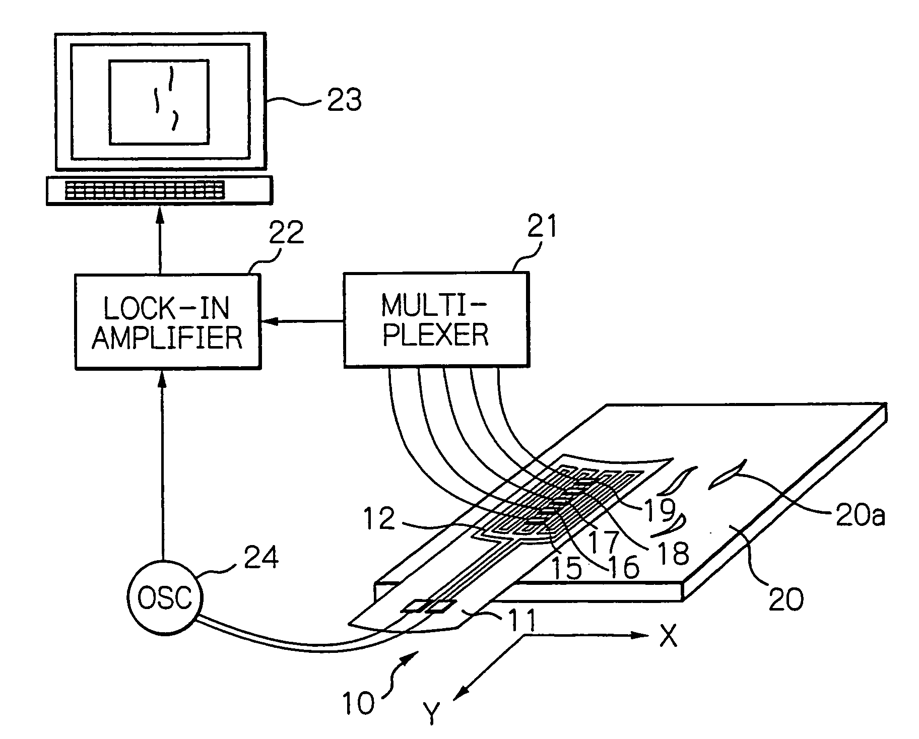
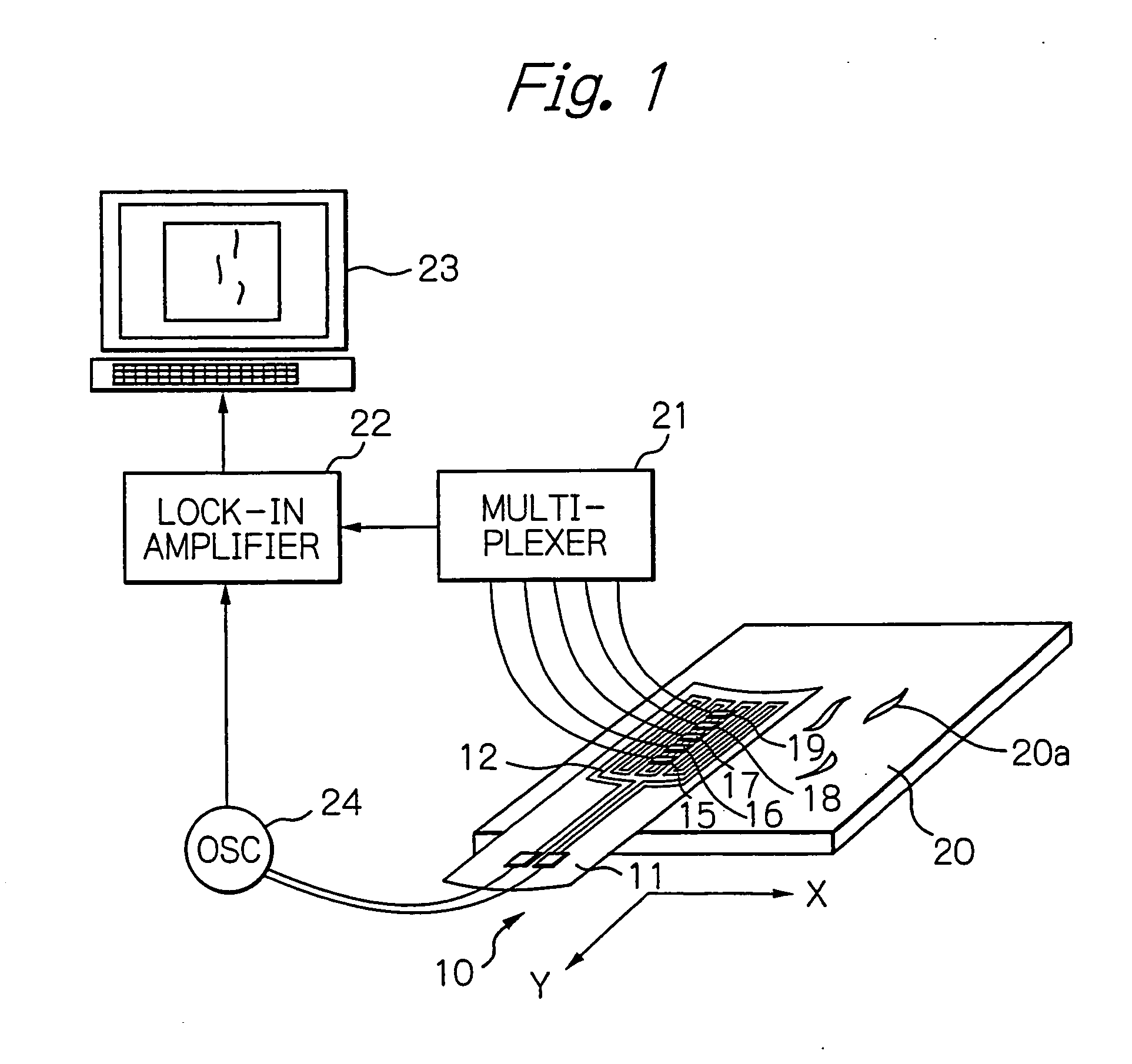
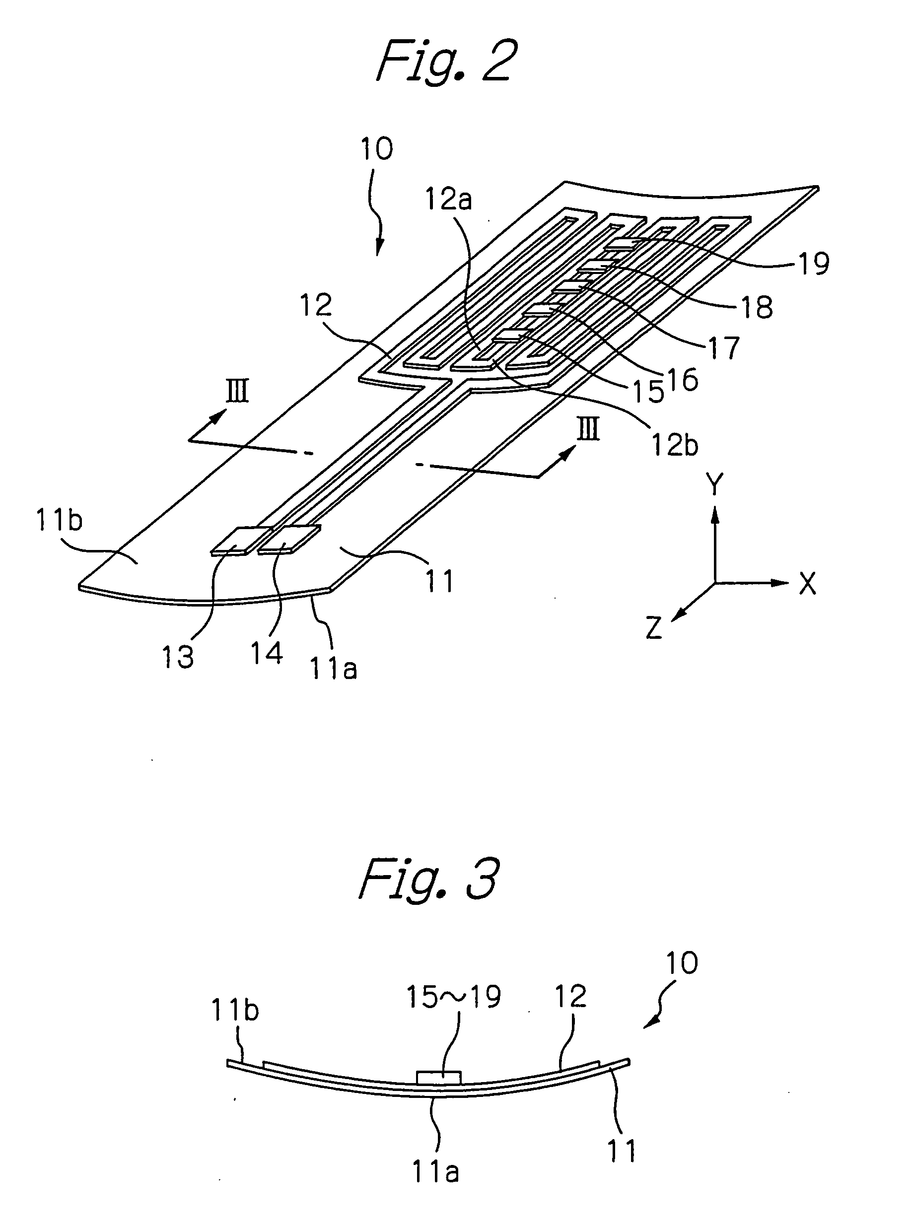
[0066]FIG. 1 shows a diagram schematically illustrating a configuration of an testing system using the eddy-current according to a preferred embodiment of the present invention, FIG. 2 shows a perspective view schematically illustrating a configuration of the ECT probe according to the embodiment in FIG. 1, and FIG. 3 shows a cross-sectional view taken along with line III-III in FIG. 2.

[0067] In these figures, reference numeral 10 indicates an ECT probe, 11 indicates its flexible substrate formed of an insulative material such as polyimide, 12 indicates a meander-type exciting coil including coil conductors formed as a planar pattern turned back on the opposite surface 11b to the measurement surface 11a of the substrate 11, 13 and 14 indicate a pair of electrode terminals formed on the substrate 11, which is connected electrically to both ends of the exciting coil 12, 15 to 19 indicate thin-film chips bonded on the exciting coil 12, each of which is mounted with a GMR element (eddy...


PUM

PropertyMeasurementUnit
magnetic fieldaaaaaaaaaa
eddy-currentaaaaaaaaaa
Eddy-current testingaaaaaaaaaa

Abstract

An eddy-current probe according to the present invention comprises: a substrate having a first surface facing to a subject to be tested and a second surface opposite to said first surface; an exciting coil formed on the second surface, having a pair of current lines in parallel with each other through which exciting currents flow in opposite directions to each other during testing, for generating an alternate magnetic field applied to the subject by the exciting currents; and at least one eddy-current sensor positioned on a central axis between the pair of current lines on the second surface of the substrate, for detecting a magnetic field generated newly from the subject by an eddy-current induced by the alternate magnetic field. The substrate has a non-planar form having at least one convex-surface portion on the first surface, and the at least one eddy-current sensor is formed on at least one concave-surface portion formed on the second surface, which is corresponding to the at least one convex-surface portion.

Description

PRIORITY CLAIM [0001] This application is a divisional application of application Ser. No. 11 / 203,252, filed Aug. 15, 2005, which is a divisional application of application Ser. No. 10 / 938,541, filed Sep. 13, 2004. [0002] This application claims priority from Japanese patent application No. 2003-326174, filed on Sep. 18, 2003, which is incorporated herein by reference.BACKGROUND OF THE INVENTION [0003] 1. Field of the Invention [0004] The present invention relates to an eddy-current probe that is able to detect object's shapes, defects and so on nondestructively. [0005] 2. Description of the Related Art [0006] Eddy-current testing (ECT) technique is frequently utilized for nondestructive testing of distorted surfaces of important metal machine parts used in a nuclear power plant, an airplane and so on, such as turbine blades, various pipes and airplane wings. Generally, such an ECT probe using the eddy-current includes mainly an exciting coil and a detector coil for detecting a magn...

Claims


Application Information

Patent Timeline
Patent Type & Authority Applications(United States)
IPC IPC(8): G01N27/82
CPCG01N27/82G01N27/9033G01N27/9006
Inventor SHOJI, SHIGERU
Owner TDK CORPARATION
Why Eureka
Try Eureka