Undulator and method of operation thereof

Active Publication Date: 2006-07-20
KERNFORSCHUNGSZENTRUM KARLSRUHE GMBH
View PDF0 Cites 21 Cited by
  • Summary
  • Abstract
  • Description
  • Claims
  • Application Information

AI Technical Summary

Benefits of technology

[0010] In an undulator for the generation of synchrotron radiation from a particle beam introduced into the undulator, two partial undulators are provided each comprising a conductor of superconductive material which, when a current is conducted therethrough, generates an undulator field that extends perpendicularly to the cur

Problems solved by technology

The first solution requires expensive mechanical structures to permit movement of the magnets under the high forces effective on the magnets.
A variant of this equipment is disclosed in JP 103 03 99

Method used


Image

  • Undulator and method of operation thereof
  • Undulator and method of operation thereof
  • Undulator and method of operation thereof

Examples


Example

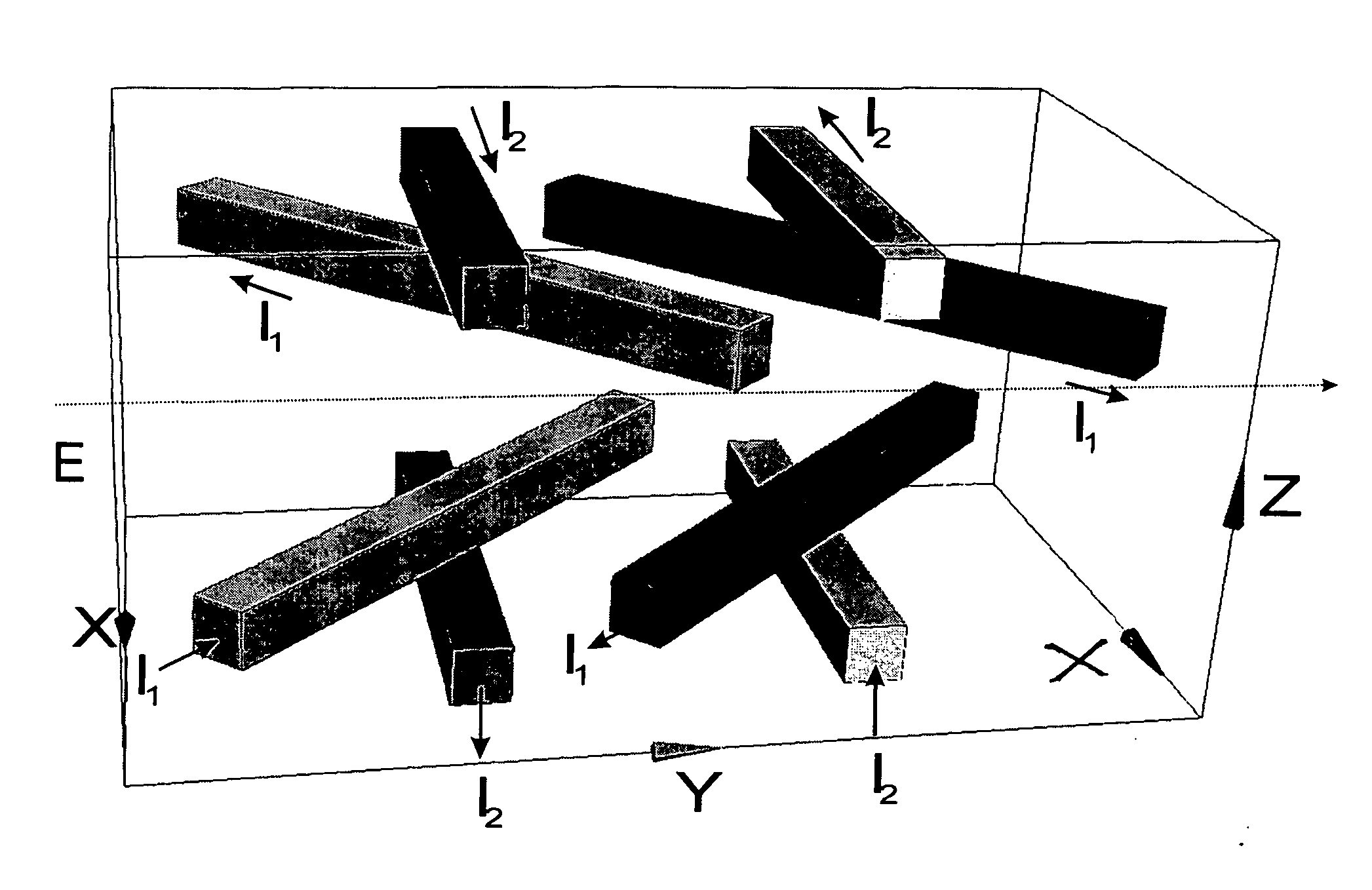
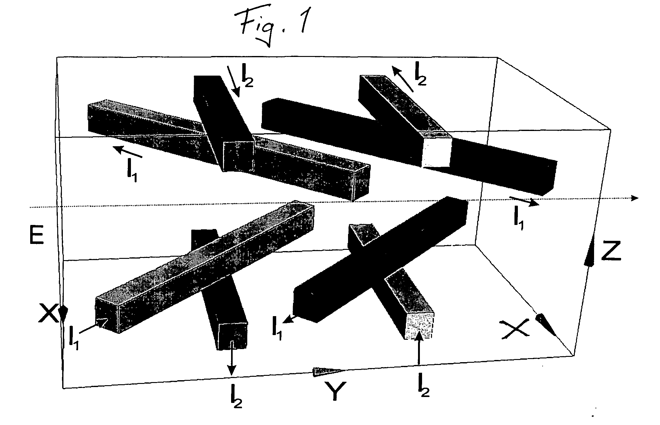
[0015] The principal features of an undulator according to the invention will be explained on the basis of FIG. 1. The operation of an undulator with variable polarization direction in accordance with the invention is based on an arrangement of two different conductors (coils) of superconductive material which can be independently energized.

[0016] An undulator according to the invention consequently comprises two superconductive partial undulators, that is: [0017] a) a first partial undulator including a superconductive high-capacity coil or conductor through which the current I1 flow and which with regard to its distance from the electron beam E is designated the inner undulator, and [0018] b) a second partial undulator including a superconductive high capacity conductor through which the current I2 flows and which is disposed at a greater distance from the electron beam E than the second partial undulator and, therefore, is designated the outer undulator. The two currents I1 and ...


PUM


Abstract

In an undulator for the generation of synchrotron radiation from a particle beam introduced into the undulator, two partial undulators are provided each comprising a conductor of superconductive material which, when a current is conducted therethrough, generates an undulator field that extends perpendicularly to the current flow, and the superconductive conductors are arranged in the individual partial undulators such that the undulator fields generated are not parallel, whereby, by controlling the energization of the two partial undulators, the polarization direction of the synchrotron radiation can be adjusted without mechanical movements.

Description

[0001] This is a Continuation-in-Part Application of PCT / EP2004 / 013466 filed 27 / 11 / 04 and claiming priority of German Application 103 58 225.8 filed Dec. 12, 2003.BACKGROUND OF THE INVENTION [0002] The invention relates to undulators which serve as a source of electromagnetic radiation called below also light, which is generated from a particle stream (for example of electrons) passing through the undulator and to a method of operating such an undulator. Undulators are used particularly for the generation of x-rays in synchrotron radiation sources. [0003] World with numerous attempts have been made to construct undulators from permanent magnets in such a way that the polarization direction of the light emitted by the undulators can be changed by mechanical movements. An overview of the techniques can be found in H. Onuki and P. Elleaume, Undulators, Wigglers, and their Applications, chapter 6, Polarizing undulators and wigglers, Tayler and Francis, 2003. According to the state of th...

Claims


Application Information

Patent Timeline
IPC IPC(8): H01F6/00H05H7/04
CPCH05H7/04
Inventor ROSSMANITH, ROBERTSCHINDLER, UWE
Owner KERNFORSCHUNGSZENTRUM KARLSRUHE GMBH
Why Eureka
Try Eureka