Non-planar prism

a prism and non-planar technology, applied in the field of biometric imaging technology, can solve the problems of not all portions of the palm print will be imaged during scanning, the palm naturally curves, and the loss of biometric information

Inactive Publication Date: 2006-07-20
CROSS MATCH TECH
View PDF99 Cites 16 Cited by
  • Summary
  • Abstract
  • Description
  • Claims
  • Application Information

AI Technical Summary

Problems solved by technology

One problem with conventional palm live scanner systems is that a palm naturally curves, while a typical platen has a flat planar surface upon which a palm is placed.
Thus, there is a chance that not all portions of the palm print will be imaged during scanning.
If this occurs, biometric information can be lost.
Also, in many live scanners, increasing the surface area of a flat platen requires a significant increase in the size of a camera being used to detect images on the platen.
Large area cameras or sets of cameras can dramatically increase cost and complexity.
As a result, the size of the surface area of a flat platen is limited in many live scanners to a size of an average palm or smaller.

Method used


Image

  • Non-planar prism
  • Non-planar prism
  • Non-planar prism

Examples


Embodiment Construction

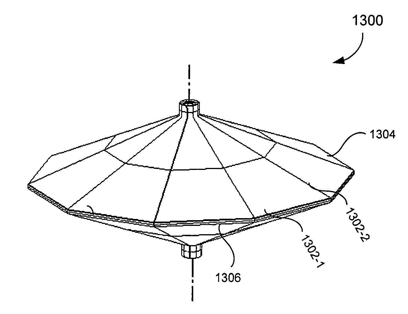
[0028] Embodiments of the present invention provide a system and method for scanning all or part of a hand print for one or more hands positioned on a non-planar portion of a prism. The non-planar portion can be symmetrical about an axis of symmetry of the prism. Typically, a palm pocket, writer's palm, or the like, is hard to capture on a flat surface. In contrast, the non-planar portion of the prism according to embodiments of the present invention provides a form so that the palm pocket, writer's palm, or the like, can be captured. Hand and / or finger characteristic data can also be captured, for example hand geometry (e.g., finger lengths and spacing between fingers).

[0029] The prism can also include a positioning device (e.g., a hand-locating feature) than can be used to position a hand based on a point between a thumb and an index finger, between any other two fingers, a full hand on one side of the alignment device, both hands with each hand on either side of the alignment de...


PUM


Abstract

A system and method are provided for scanning all or part of a hand print for one or more hands positioned on a non-planar portion of a prism. The non-planar portion can be symmetrical about an axis of symmetry of the prism. Typically, a palm pocket, writer's palm, or the like, is hard to capture on a flat surface. In contrast, the non-planar portion of the prism according to embodiments of the present invention provides a form so that the palm pocket, writer's palm, or the like, can be captured. Hand and / or finger characteristic data can also be captured, for example hand geometry (e.g., finger lengths and spacing between fingers). The prism can also include a positioning device (e.g., a hand-locating feature) than can be used to position a hand based on a point between a thumb and an index finger, between any other two fingers, a full hand on one side of the alignment device, both hands with each hand on either side of the alignment device, or to capture writer's palm and / or writer's palm and fingertip images.

Description

CROSS REFERENCE TO RELATED APPLICATIONS [0001] This application is a continuation of U.S. application Ser. No. 10 / 725,539, filed Dec. 3, 2003, which claims the benefit of U.S. Provisional Application No. 60 / 431,240, filed Dec. 6, 2002, and U.S. Provisional Application No. 60 / 491,537, filed Aug. 1, 2003, all of which are incorporated herein by reference in their entireties.BACKGROUND OF THE INVENTION [0002] 1. Field of the Invention [0003] The present invention pertains to biometric imaging technology, and in particular, to live scanning of prints. [0004] 2. Background Art [0005] Biometrics is a science involving the analysis of biological characteristics. Biometric imaging captures a measurable characteristic of a human being for identity and other related purposes. Print capture and recognition is an important biometric technology. Law enforcement, banking, voting, and other industries increasingly rely upon prints as a biometric to store, recognize or verify identity. Generally, a...

Claims


Application Information

Patent Timeline
Patent Type & Authority Applications(United States)
IPC IPC(8): G02B5/04G06K9/00
CPCG06K9/00013G06K9/00046G06V40/1324
Inventor MCCLURG, GEORGE W.CARVER, JOHN F.EBRIGHT, FRANK L.
Owner CROSS MATCH TECH
Why Eureka
Try Eureka