Image forming apparatus

Inactive Publication Date: 2006-07-20
S PRINTING SOLUTION CO LTD
View PDF4 Cites 41 Cited by
  • Summary
  • Abstract
  • Description
  • Claims
  • Application Information

AI Technical Summary

Benefits of technology

[0008] An aspect of the present invention provides an image forming apparatus wherein a us

Problems solved by technology

Meanwhile, since the photosensitive medium and a developer container to contain the developer each have a limited lifespan, each should be replaced after the developer is exhausted.
Thus, when the user separates the development cartridge from the image forming app

Method used


Image

  • Image forming apparatus
  • Image forming apparatus
  • Image forming apparatus

Examples


Embodiment Construction

[0023] Reference will now be made in detail to the present embodiments of the present invention, examples of which are illustrated in the accompanying drawings, wherein like reference numerals refer to the like elements throughout. The embodiments are described below in order to explain the present invention by referring to the figures.

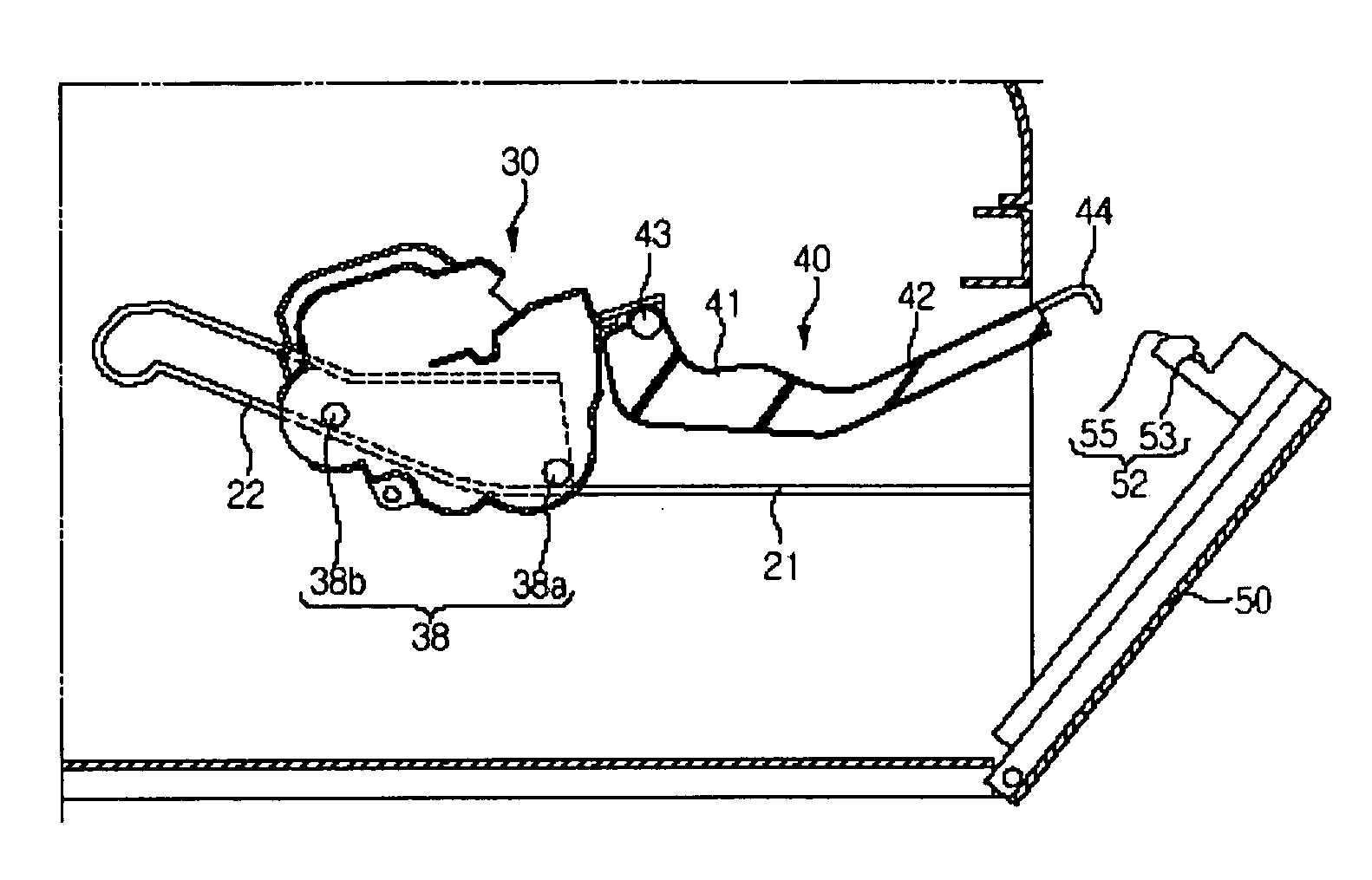
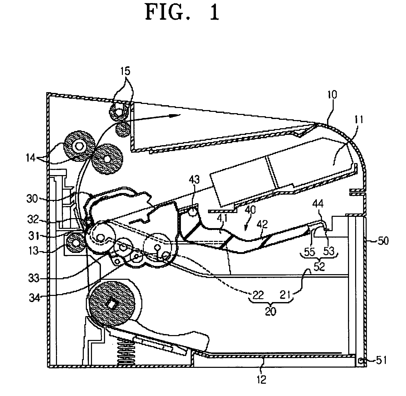
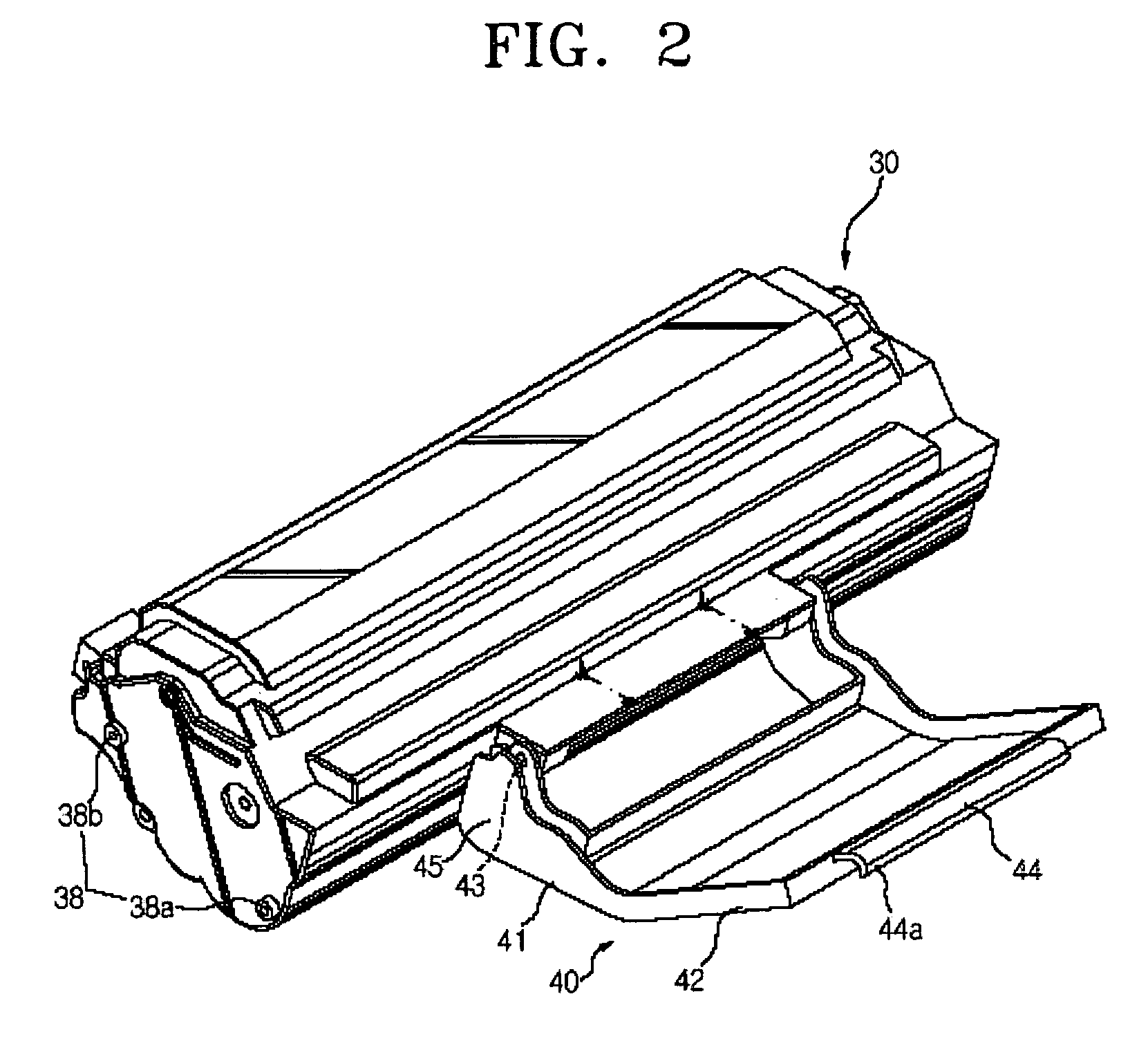
[0024]FIG. 1 is a view showing a construction of the image forming apparatus in which a development cartridge 30 according to an embodiment of the present invention is mounted within an inner portion of a main body frame 10.

[0025] As shown in the drawings, a laser scanning unit 11 scans a laser beam based on image information and forms an electrostatic latent image on a photosensitive drum 31 of the development cartridge 30 that is to be charged with a constant electric potential. A developing roller 33 applies a developer on the photosensitive drum 31 on which the electrostatic latent image is formed, and forms a visible image thereon. During such ...


PUM


Abstract

An image forming apparatus, including a main body frame, a cover which is pivotally coupled to the main body frame, to occupy and move between a first position at which the cover is closed and a second position at which the cover is open, and a development cartridge, which is detachably mounted to an inner portion of the main body frame, and a handle connected to the cover so as to move the development cartridge in the outside direction of the main body frame when the cover is moved from the first position to the second position.

Description

CROSS-REFERENCE TO RELATED APPLICATIONS [0001] This application claims the benefit of Korean Application No. 2005-4989, filed Jan. 19, 2005, in the Korean Intellectual Property Office, the disclosure of which is incorporated herein by reference. BACKGROUND OF THE INVENTION [0002] 1. Field of the Invention [0003] An aspect of the present invention relates to an image forming apparatus, and, more particularly, to an image forming apparatus in which a development cartridge is detachable. [0004] 2. Description of the Related Art [0005] Generally, an image forming apparatus adopting an electro-photographic method, such as a laser beam printer, a digital copier and a multifunctional device scans a photosensitive medium with a laser beam, forms an electrostatic latent image, and applies a developer to the photosensitive medium on which the electrostatic latent image is formed, so as to form a visible image. During the image forming process, a printing medium is supplied from a paper feed c...

Claims


Application Information

Patent Timeline
IPC IPC(8): G03G15/00G03G21/18
CPCG03G21/1846G03G15/0868G03G15/0896G03G2221/1846B65D83/32B65D83/48B65D83/207
Inventor KWEON, DAE-SEOB
Owner S PRINTING SOLUTION CO LTD
Why Eureka
Try Eureka