Soft start, high inertia flywheel for tub grinders

a flywheel and high inertia technology, applied in the field of flywheels, can solve the problems of affecting the operation of the flywheel, the negative effect of adding weight, and the over-weight of the driveline, and achieve the effects of preventing the jamming of the tub grinder, high inertia, and stabilizing the rotational speed

Active Publication Date: 2006-07-27
COBLE LEONARD
View PDF8 Cites 3 Cited by
  • Summary
  • Abstract
  • Description
  • Claims
  • Application Information

AI Technical Summary

Benefits of technology

[0008] The invention consists of a high inertia flywheel for a tub grinder to stabilize the rotational speed of an engine-driven hammermill of the tub grinder and to act to prevent jamming of the tub grinder. The high inertia flywheel is attached to either the input or output shaft of the hammermill and is located outside the confines of the tub. A slip clutch or fluid coupling interconnects the flywheel to the hammer mill. A control is provided from adjusting the connection between the engine and the flywheel.

Problems solved by technology

The prior art has failed to address these issues in that most tub grinders have increased the hammermill diameters to increase the grinding production.
This has the negative effect of also adding weight.
Large torque limiters through the driveline force the driveline to be oversized.

Method used


Image

  • Soft start, high inertia flywheel for tub grinders
  • Soft start, high inertia flywheel for tub grinders
  • Soft start, high inertia flywheel for tub grinders

Examples


Embodiment Construction

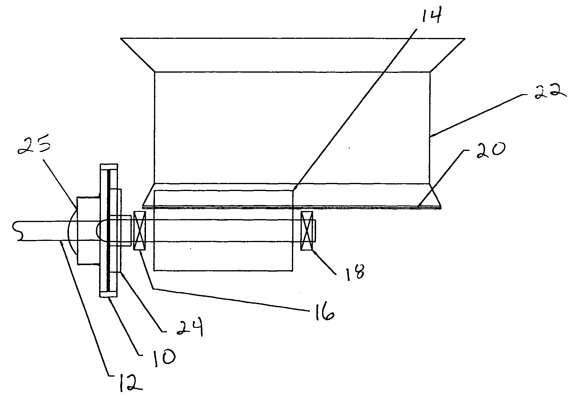
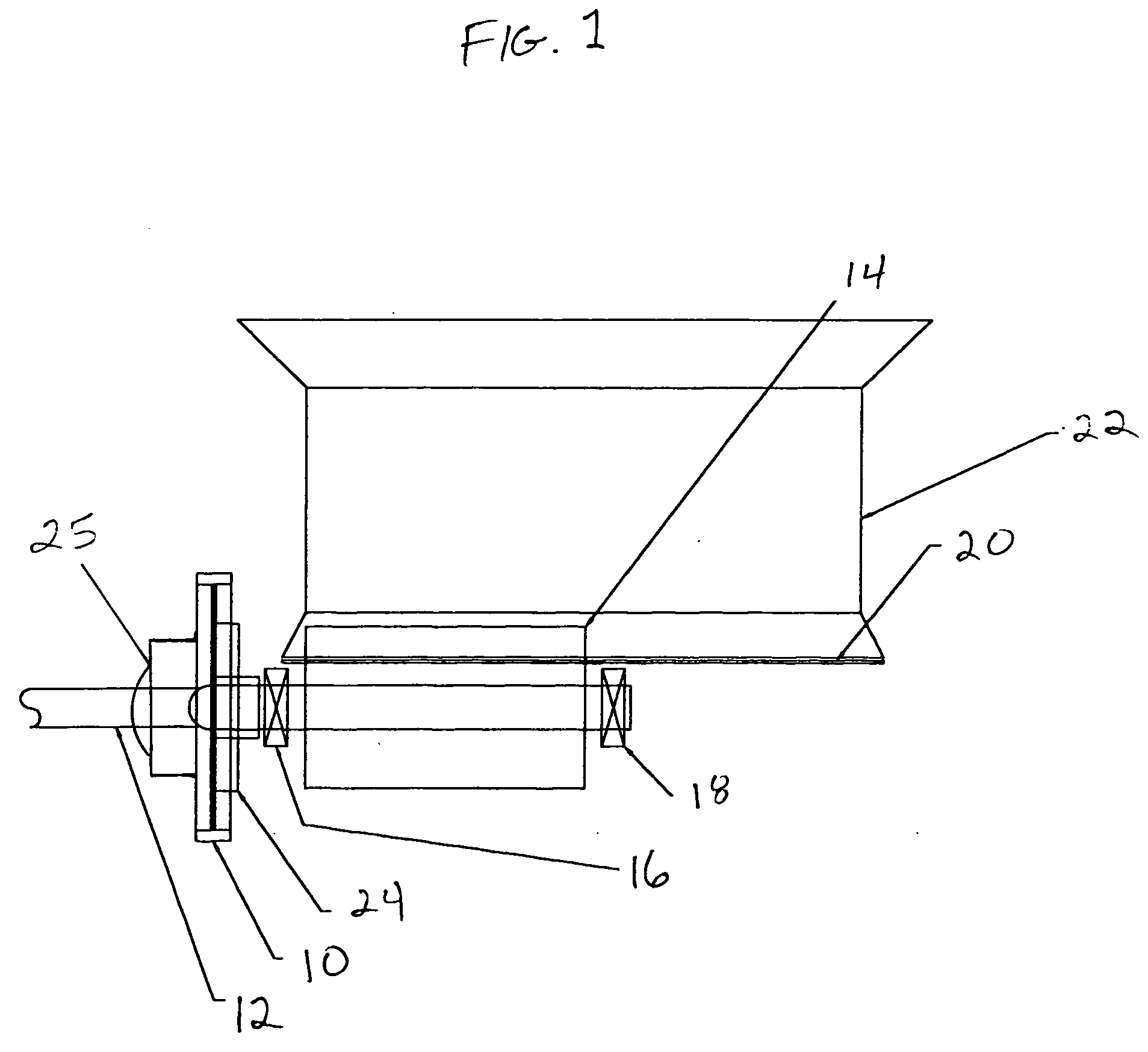
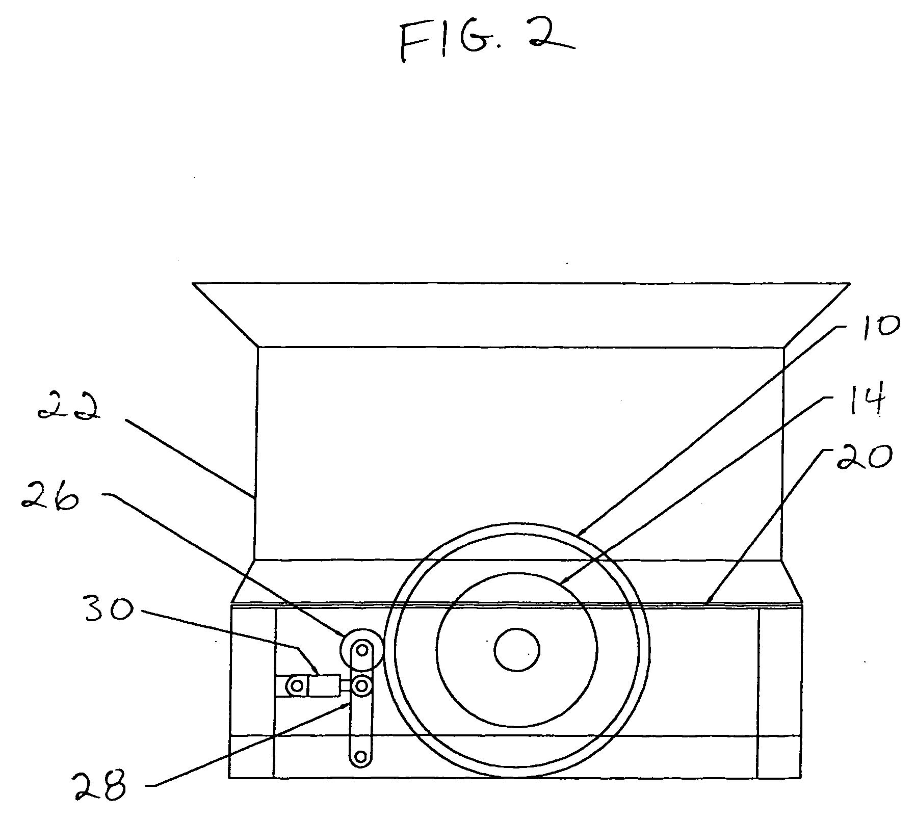
[0015] Referring to the drawings, there is illustrated in FIG. 1, generally at 10, a flywheel of a preferred embodiment of the present invention, which is part of a mobile tub grinder. The flywheel 10 is mounted on the input end of a drive shaft 12 of a hammermill 14. The drive shaft 12 is driven by an engine (not shown) and is mounted in a pair of bearings, input end bearings 16 and output end bearings 18. Rotation of the drive shaft 12 rotates the hammermill 14 between the pair of bearings 16 and 18 and below the floor 20 of the tub 22 of the tub grinder. As best illustrated in FIG. 2, the outer periphery of the hammermill 14 extends above the floor 20 of the tub 22 to come into contact with material inside the tub 22 that is to be ground or comminuted by the tub grinder.

[0016] The flywheel 10 is preferably mounted to the input side of the hammermill 14, but may optionally be mounted on the output side if the hammermill 14 was situated on the opposite side of the tub 22. By mount...


PUM


Abstract

The invention is a high inertia flywheel for a tub grinder to stabilize the rotational speed of a hammermill of the tub grinder and to act to prevent jamming of the tub grinder. A high inertia flywheel attached to either the input or output shaft of the hammermill and outside the confines of the tub. A slip clutch or fluid coupling interconnects the flywheel to the hammermill. A motor spins the flywheel to a desired speed before the clutch is engages or disengaged. A control is used for adjusting the connection between the motor means and the flywheel.

Description

[0001] This application claims the benefit of U.S. Provisional Application No. 60 / 639,385, filed Dec. 27, 2004.BACKGROUND OF THE INVENTION [0002] The invention relates generally to flywheels and, more specifically, to a soft start, high inertia flywheel for use with tub grinders. [0003] Flywheels have been used for many years dating back to the steam engine and single cylinder gas engines to produce inertia to carry the load between piston firings. Many mechanical systems use flywheels to stabilize the rotation of the engine and the driven equipment. [0004] A tub grinder has a tub-shaped enclosure including a circular floor, generally cylindrical sidewalls and an open top. An example of a tub grinder is described in U.S. Pat. No. 5,950,942. Material to be comminuted by the tub grinder is added to the tub through the open top. A hammermill rotates at a high speed along a typically horizontal axis below the floor of the tub. The outer periphery of the hammermill extends above the floo...

Claims


Application Information

Patent Timeline
Patent Type & Authority Applications(United States)
IPC IPC(8): B02C13/26
CPCB02C13/30B02C18/067B02C18/24
Inventor COBLE, LEONARD
Owner COBLE LEONARD
Why Eureka
Try Eureka