
Robot space trajectory transition method

A robot and trajectory technology, applied in the direction of manipulators, program-controlled manipulators, manufacturing tools, etc., can solve the problems of reducing robot trajectory accuracy, reducing robot production efficiency, and robot operation jitter, so as to improve operating efficiency, improve motion stability, and speed smooth effect

Active Publication Date: 2019-04-16
合肥哈工图南智控机器人有限公司
View PDF7 Cites 32 Cited by
  • Summary
  • Abstract
  • Description
  • Claims
  • Application Information

AI Technical Summary

Problems solved by technology

[0003] In the prior art, the main method used by major manufacturers is to use circular arc trajectory transition between two adjacent two straight line segments. Although the arc is tangent to the two straight lines before and after, but due to the curvature is a constant, so even if uniform motion is used in the arc transition trajectory stage, the centripetal acceleration is also a constant, but the centripetal acceleration in the straight line segment is 0, so when the arc trajectory transition is adopted, at the beginning and end of the transition trajectory , the centripetal acceleration changes from 0 to a constant that is not 0, forming an acceleration shock, causing the robot to vibrate and reducing the trajectory accuracy of the robot; Start to accelerate, although the speed is stable, when there are multiple straight-line trajectories, it will cause the robot to start and stop repeatedly, reducing the production efficiency of the robot when it is running, which is not advisable

Method used


Image

  • Robot space trajectory transition method
  • Robot space trajectory transition method
  • Robot space trajectory transition method

Examples


Embodiment Construction

[0038] The present invention will be described in detail below in conjunction with the accompanying drawings and specific embodiments, wherein the schematic embodiments and descriptions are only used to explain the present invention, but are not intended to limit the present invention.

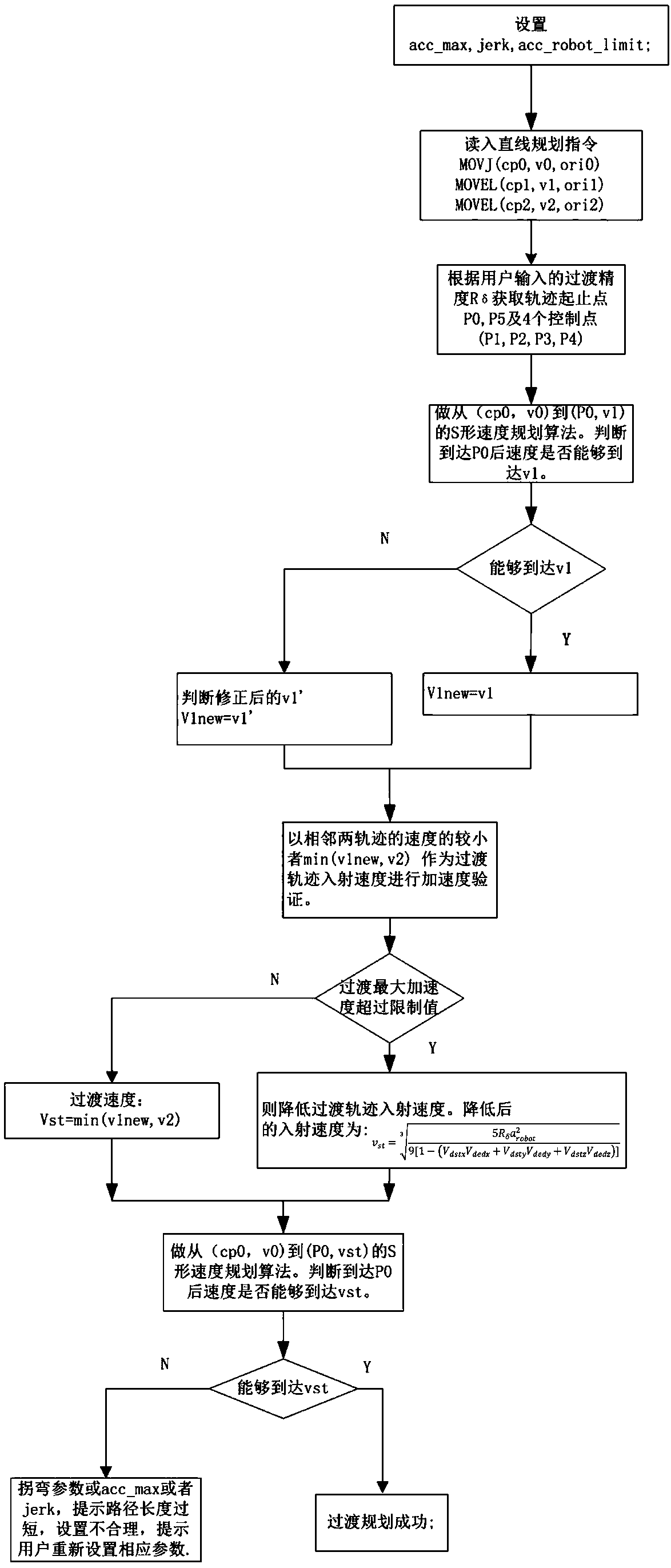
[0039] See attached figure 1 , which shows a schematic flow diagram of the method of the present invention, the specific steps of the method are described as follows:

[0040] Step S1: Set the maximum acceleration acc_max, the jerk jerk, and the acceleration upper limit value a for acceleration verification during the S-shaped speed planning of the robot robotLimit .

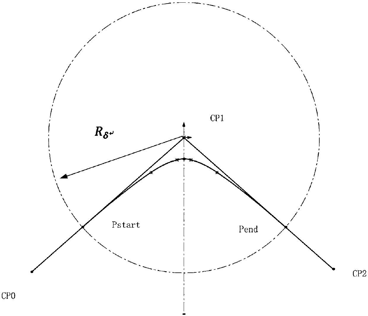
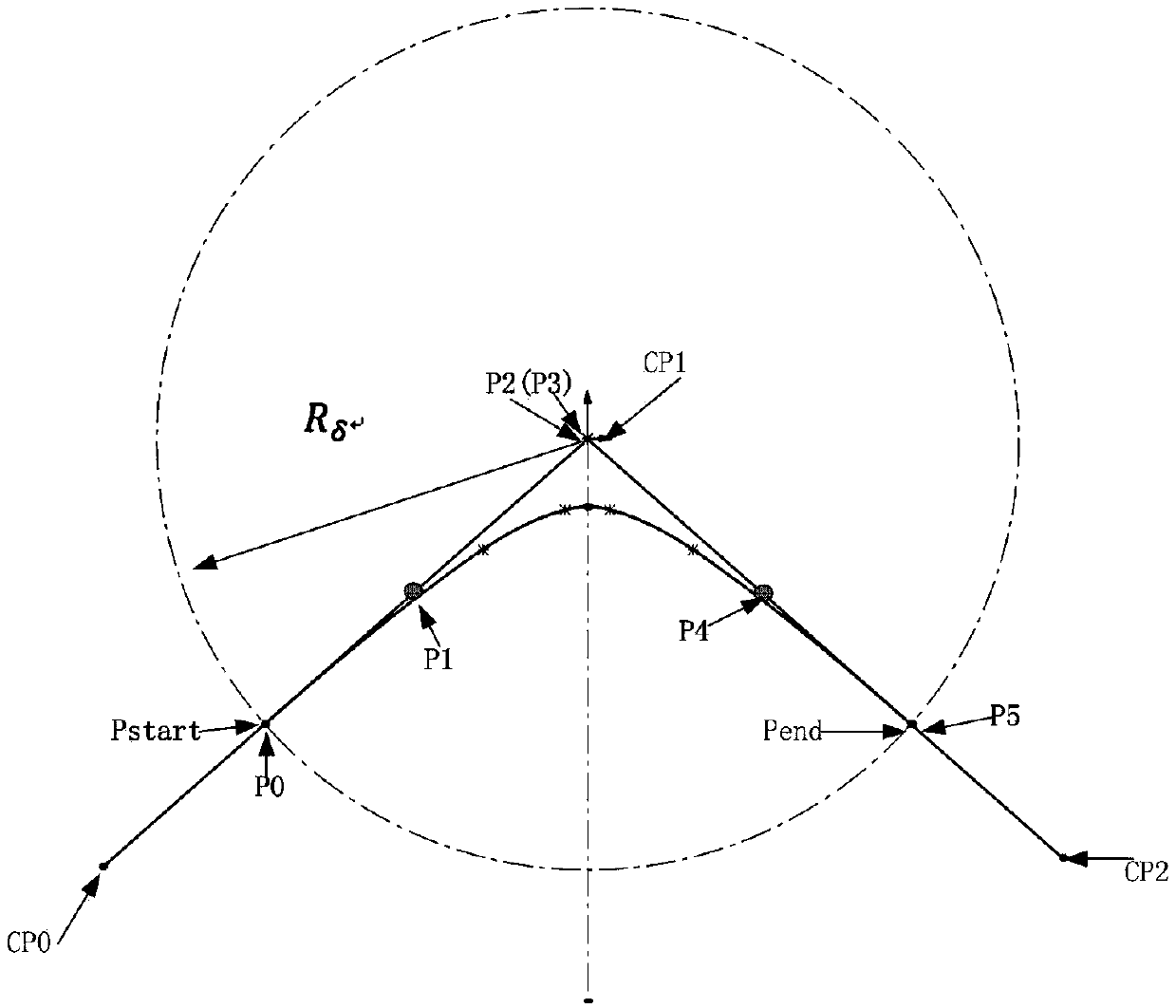
[0041] Step S2: Read the robot motion command and command parameters, the motion command indicates two continuous straight-line motion trajectories, and the command parameters include the transition accuracy R δ , the transition precision represents the precision value of the transition curve of the two linear motion trajectorie...


PUM


Abstract

The invention relates to a robot space trajectory transition method which solves the problem about smooth trajectory transition of a robot in the continuous linear motion process. According to the method, a five-time Bezier curve is combined with a parameter adaptive S-shaped velocity planning algorithm, and a transition trajectory of two adjacent straight lines is constructed in cooperation withprospect planning stage transition trajectory acceleration checking and a transition speed adaptive algorithm. The transition trajectory curve obtained by the method is smooth, the speed of starting and stopping points of the transition trajectories is smooth, the acceleration speed is continuous, the system motion stability is greatly improved, and the transition curve uniform speed can be automatically adjusted according to the specified robot tail end acceleration upper limit value and the S-shaped speed planning algorithm; and meanwhile, the robot does not need to be started and stopped repeatedly, and the working efficiency is improved.

Description

【Technical field】 [0001] The invention belongs to the field of robot motion control, and in particular relates to a method for generating trajectory transitions during continuous linear motion of a robot. 【Background technique】 [0002] At present, relying on the communication between the motion controller (card) and the servo drive to realize the movement of the robot or servo motor has become the choice of major manufacturers of robots and motion controllers. The principle is that the motion controller receives information from the host computer Robot command, analyze the robot command, and then carry out the corresponding motion command planning algorithm. During the working process, the robot usually performs continuous straight line and circular arc command operations in the work space. During continuous straight line motion, how to generate a smooth transition trajectory, save transition time, and improve work efficiency has always been a difficult problem to solve. ...

Claims


Application Information

Patent Timeline
IPC IPC(8): B25J9/16
CPCB25J9/1664
Inventor 刘鹏飞于振中杨广晓夏科睿涂凡凡孙强
Owner 合肥哈工图南智控机器人有限公司
Learn More