
System and method for characterizing a printing device

a printing device and characterization technology, applied in the field of multicolor output devices, can solve problems such as slope discontinuities, and achieve the effect of smooth color change representation

Inactive Publication Date: 2006-07-27
AGFA OFFSET BV
View PDF4 Cites 1 Cited by
  • Summary
  • Abstract
  • Description
  • Claims
  • Application Information

AI Technical Summary

Benefits of technology

"The present invention is a method and system for characterizing a printing device by using an inverse look up table. The method involves selecting sampling points based on a predetermined color value and a projection of the point in color space. This allows for a smooth representation of color changes in the reproduced images. The technical effect of the invention is improved accuracy and quality in color representation in printing devices."

Problems solved by technology

A disadvantage is that, at boundaries of neighboring cells, the model is not continuous for the first derivative and hence sometimes slope discontinuities in the modeling can be seen.

Method used


Image

  • System and method for characterizing a printing device
  • System and method for characterizing a printing device
  • System and method for characterizing a printing device

Examples


first embodiment

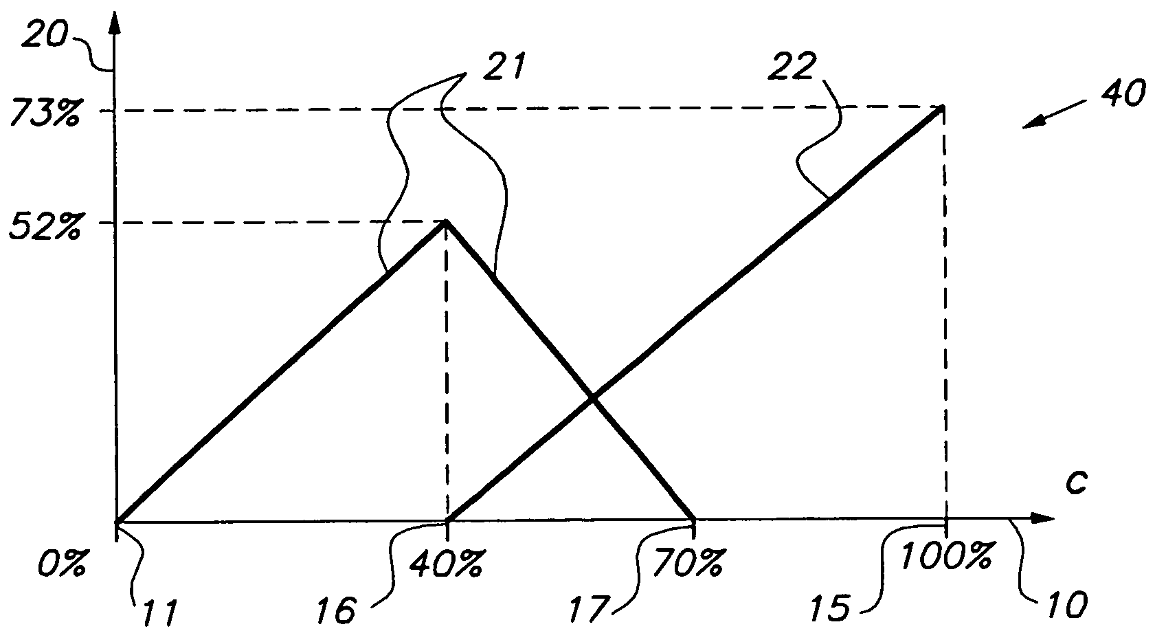
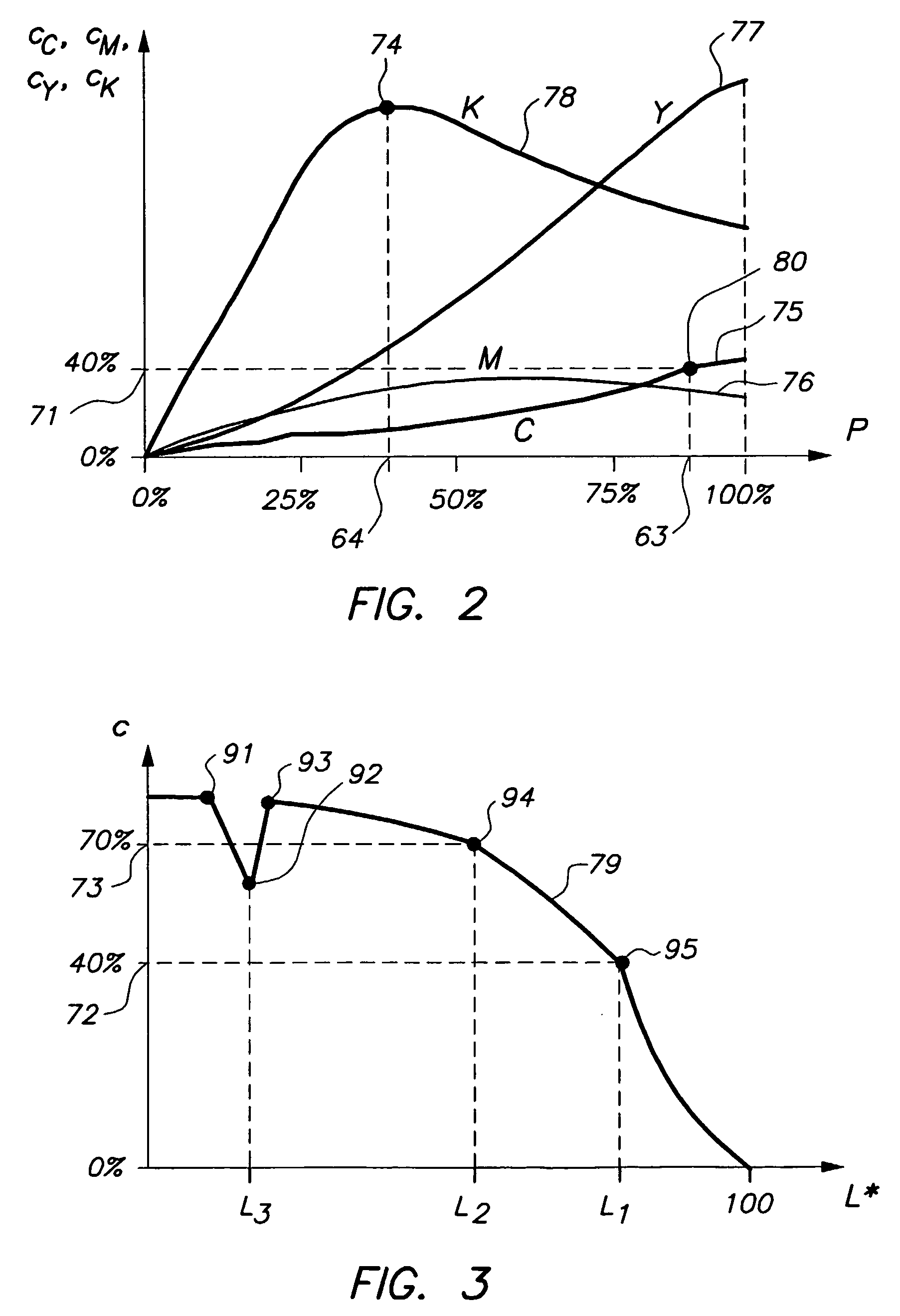
[0042] In the first embodiment, a predetermined colorant value 72, 73 is taken, such as c=40% or c=70% in FIG. 3. Such a predetermined colorant value 72, 73 may correspond to a printer model boundary point 94, 95 of the printing device, i.e. a point at a boundary of a cell of a localized printer model, as discussed already above. A predetermined colorant value 72, 73 may also correspond to a point that is called an ink changing point in this document. Ink changing points occur in case of a printing device with multi-density inks, at values for which a multi-density ink changes non-smoothly. Ink changing points are discussed further below, with reference to FIG. 4. In FIG. 4, c=40% and c=70% are ink changing points. Returning to FIG. 3, the L* values of points 94 and 95, i.e. L*=L1 and L*=L2, are taken as sampling values along the L* axis. An advantage of taking ink changing points and printer model boundary points as sampling points is that the printer behavior at such points is oft...

second embodiment

[0049] In the second embodiment discussed already above, a color separation curve is analyzed, or, which amounts to the same thing, color separation values for a plurality of points on a path in color space are analyzed, and a sampling point results from the analysis. This embodiment is discussed now with respect to FIG. 3.

[0050]FIG. 3 shows that the separation curve 79 of neutrals has a peculiar behavior at points 91-95. These points 91-95 can be found by analyzing curve 79. Points 91-95 are slope discontinuities, i.e. points where the slope of curve 79, or in other words the first derivative of the curve, is not continuous. Point 92 is also a local extremum, in this case a local minimum. As mentioned already above, a slope discontinuity may be an ink changing point or a printer model boundary point. A slope discontinuity may also originate from other sources, such as: a non-well behaved CMYK process; a sudden change in the GCR behavior in case of a CMYK printer; a sudden change re...


PUM


Abstract

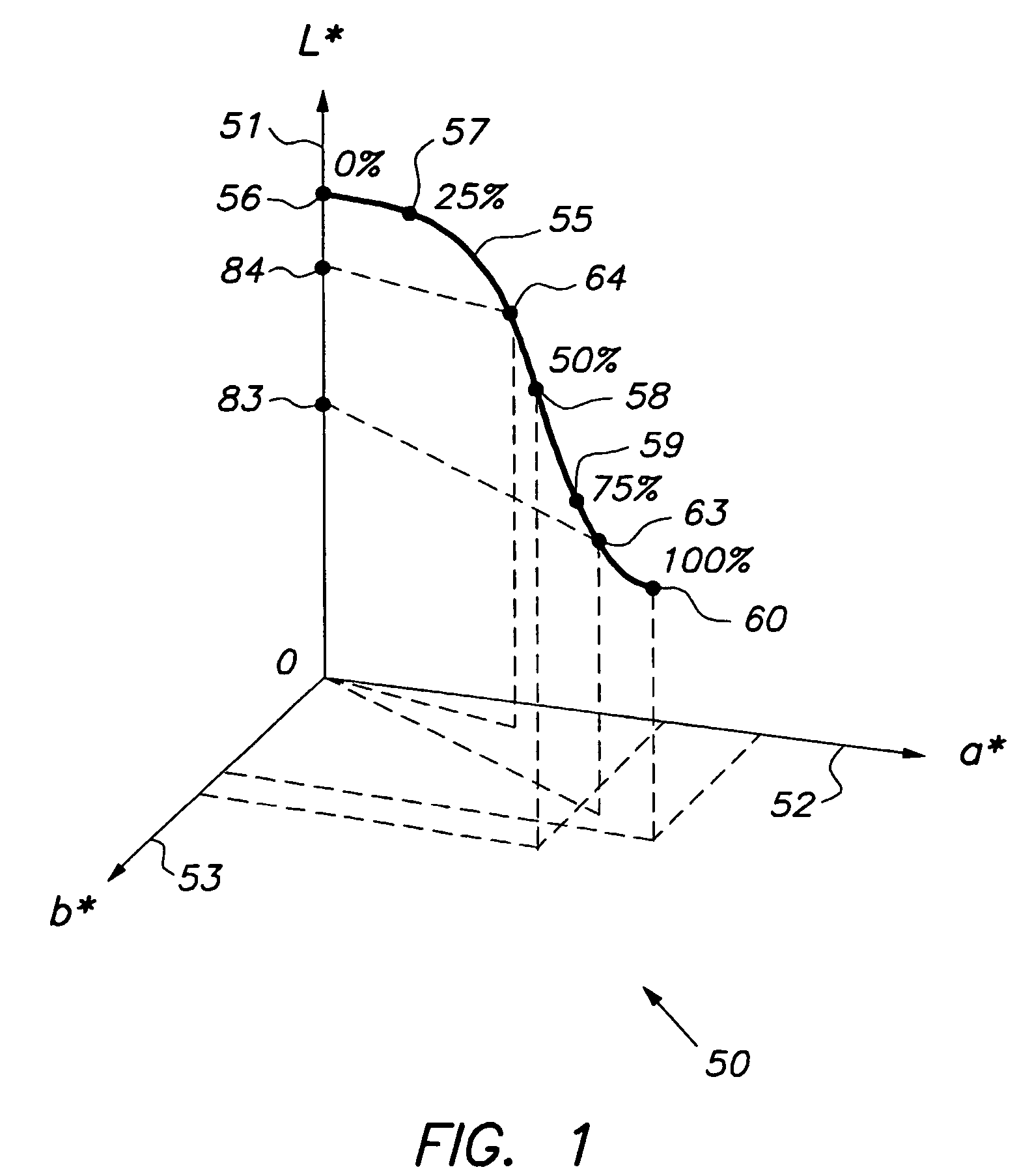
A method is used for constructing a look up table for characterizing a printing device, and a system therefore, wherein the look up table is an inverse look up table for obtaining for the printing device colorant values in a colorant space as a function of given color values in a color space. The method includes: (a) selecting an axis in the color space; (b) selecting a path in the color space; (c) determining a particular point on the path having a predetermined colorant value; (d) projecting the particular point on the axis, thus obtaining a projected point; and (e) adding the projected point to the look up table as a sampling point.

Description

FIELD OF THE INVENTION [0001] The present invention relates to the field of image rendering by means of printing devices, particularly multicolor output devices; the invention especially concerns characterization of these devices. BACKGROUND OF THE INVENTION AND DEFINITION OF TERMS [0002] Today, more and more printing systems are developed for the reproduction of color images. Several printing technologies are used such as conventional photography, electrophotography, thermal transfer, dye sublimation and ink jet systems to name a few. [0003] All these systems can be described as multidimensional color printers with n colorants, such as the CMYK (cyan, magenta, yellow and black) inks of an ink jet system. In this document it is assumed that the colorant values range from 0% (no colorant laid down on the receiving substrate such as paper) to 100% (maximum amount of colorant laid down on the receiving substrate). [0004] With colorant space is meant an n-dimensional space with n the nu...

Claims


Application Information

Patent Timeline
Patent Type & Authority Applications(United States)
IPC IPC(8): B41J2/355G01D15/10G01D15/16B41J2/525G06K15/00G06T1/00H04N1/40H04N1/46H04N1/60
CPCH04N1/40087H04N1/52H04N1/6019H04N1/6033
Inventor MAHY, MARC
Owner AGFA OFFSET BV
Learn More