

Cylindrical mixer-settler apparatus and method
a technology of cylindrical mixer and settler, which is applied in the direction of liquid displacement, separation process, filtration separation, etc., can solve the problems of reducing the effective size of the settler, aforementioned extraction process can have drawbacks, and the cost of organic solvent and extractant is relatively high, so as to achieve the effect of small recirculation and effective operation volum
- Summary
- Abstract
- Description
- Claims
- Application Information
AI Technical Summary
Benefits of technology
Problems solved by technology
Method used
Image

Examples
Embodiment Construction
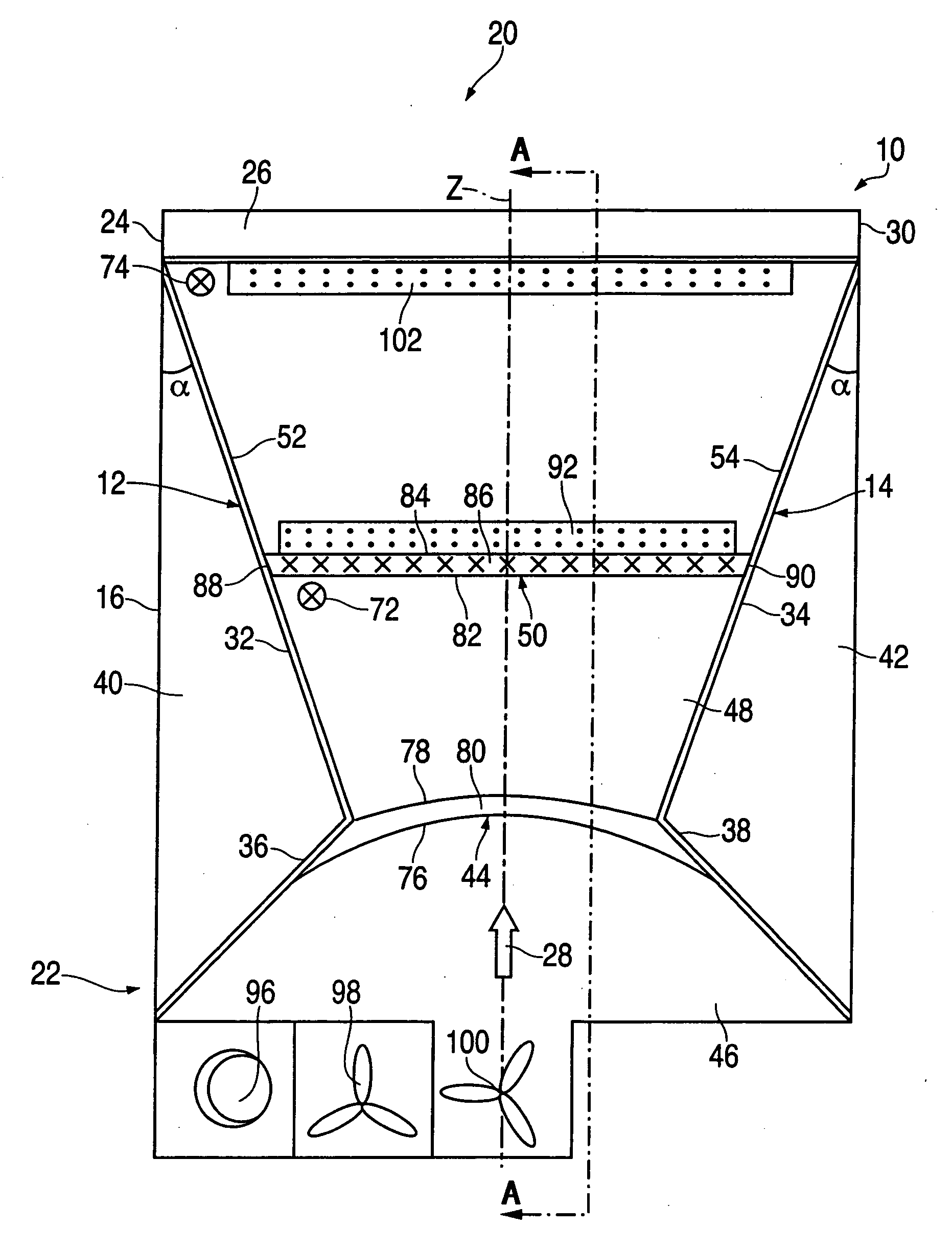
[0021] The invention will now be described with reference to the drawing figures, in which like reference numerals refer to like parts throughout. One embodiment of the present invention provides a trapezoid settler for use with solvent extraction processes. While the apparatus and method are preferably used in solvent extraction processes, the trapezoid apparatus may be employed in various other separation processes that require the separation of fluid streams, for example.
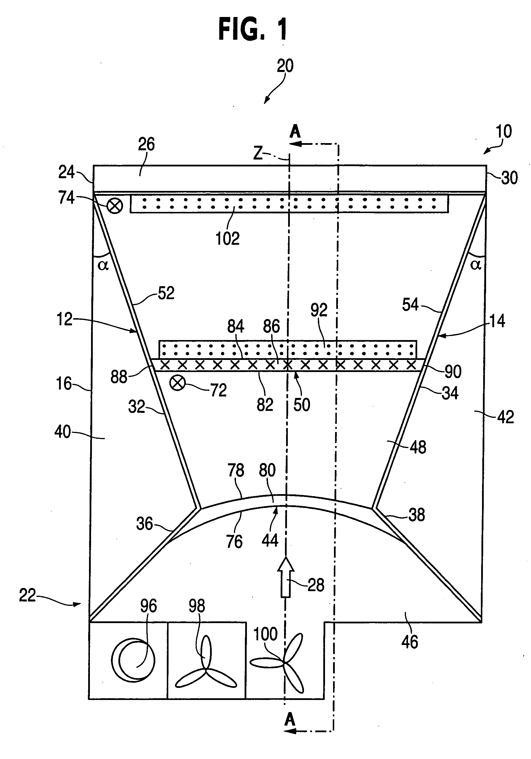
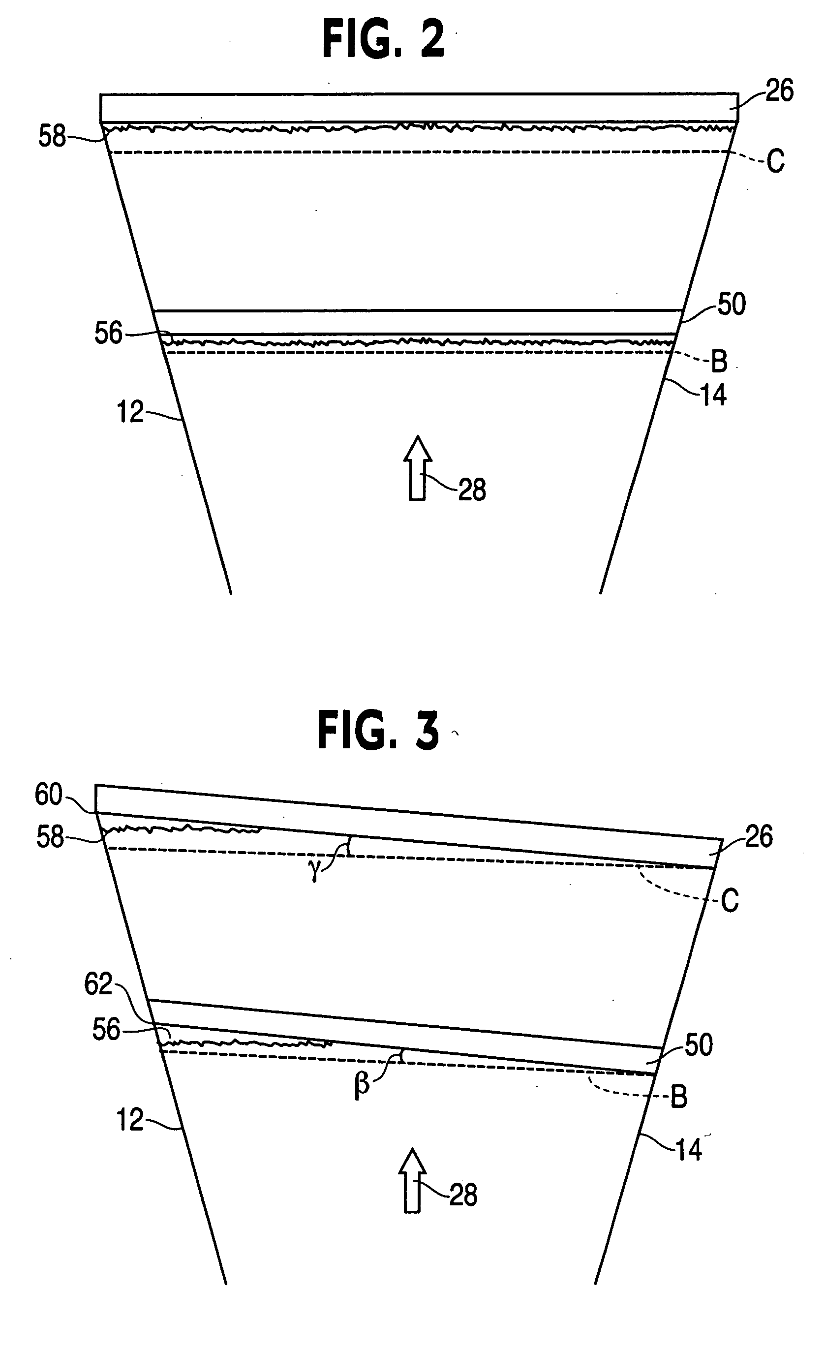
[0022] An embodiment of the present apparatus is illustrated in FIG. 1. FIG. 1 is a top view of a trapezoid settler apparatus, generally designated 10, having a longitudinal axis Z. In the embodiment depicted, the trapezoid settler apparatus 10 includes side walls 12 and 14. As illustrated in FIG. 1, the sidewalls 12 and 14 engage sidewalls 16 and 18 of a standard rectangular settler that has been retrofitted, in accordance with the present invention, to provide a trapezoid configuration. However, as discussed i...
PUM
 Abstract
Description
Claims
Application Information