
Method and apparatus for manufacturing a cutting insert

a manufacturing method and insert technology, applied in the direction of dough shaping, manufacturing tools, applications, etc., can solve the problems of inhibiting the release of the green body of the undercut element and subsequent extraction of the die cavity

Active Publication Date: 2006-07-27
ISCAR LTD
View PDF4 Cites 65 Cited by
  • Summary
  • Abstract
  • Description
  • Claims
  • Application Information

AI Technical Summary

Benefits of technology

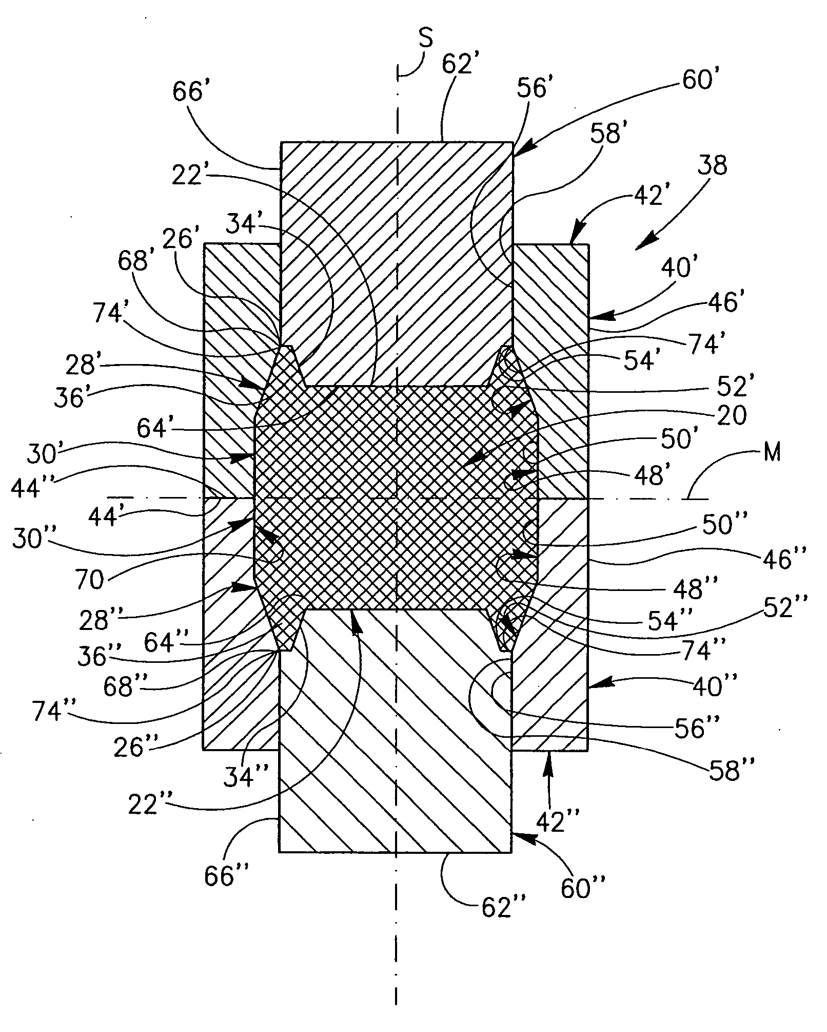
[0009] (vi) Moving the top die and punch away from the bottom die and punch to an open position, thereby enabling removal of the green body.

Problems solved by technology

However, while parts having undercut elements may generally be pressed, the undercut elements inhibit release and subsequent extraction of the compacted green body from the die cavity.

Method used


Image

  • Method and apparatus for manufacturing a cutting insert
  • Method and apparatus for manufacturing a cutting insert
  • Method and apparatus for manufacturing a cutting insert

Examples


Embodiment Construction

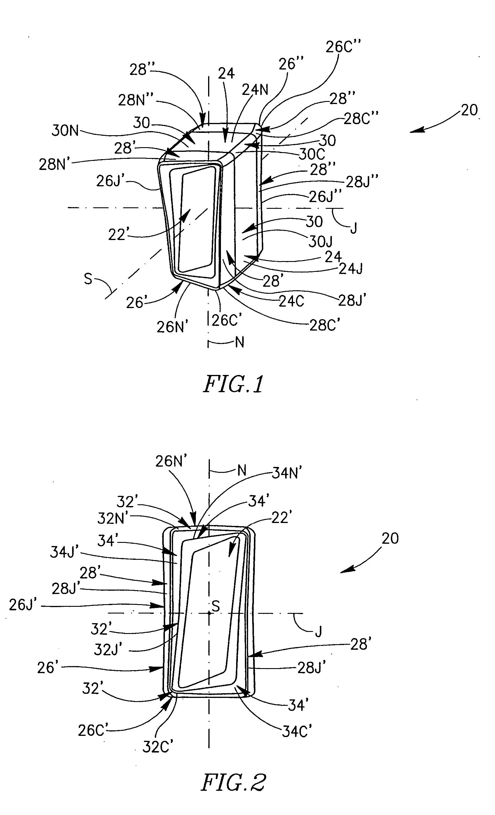
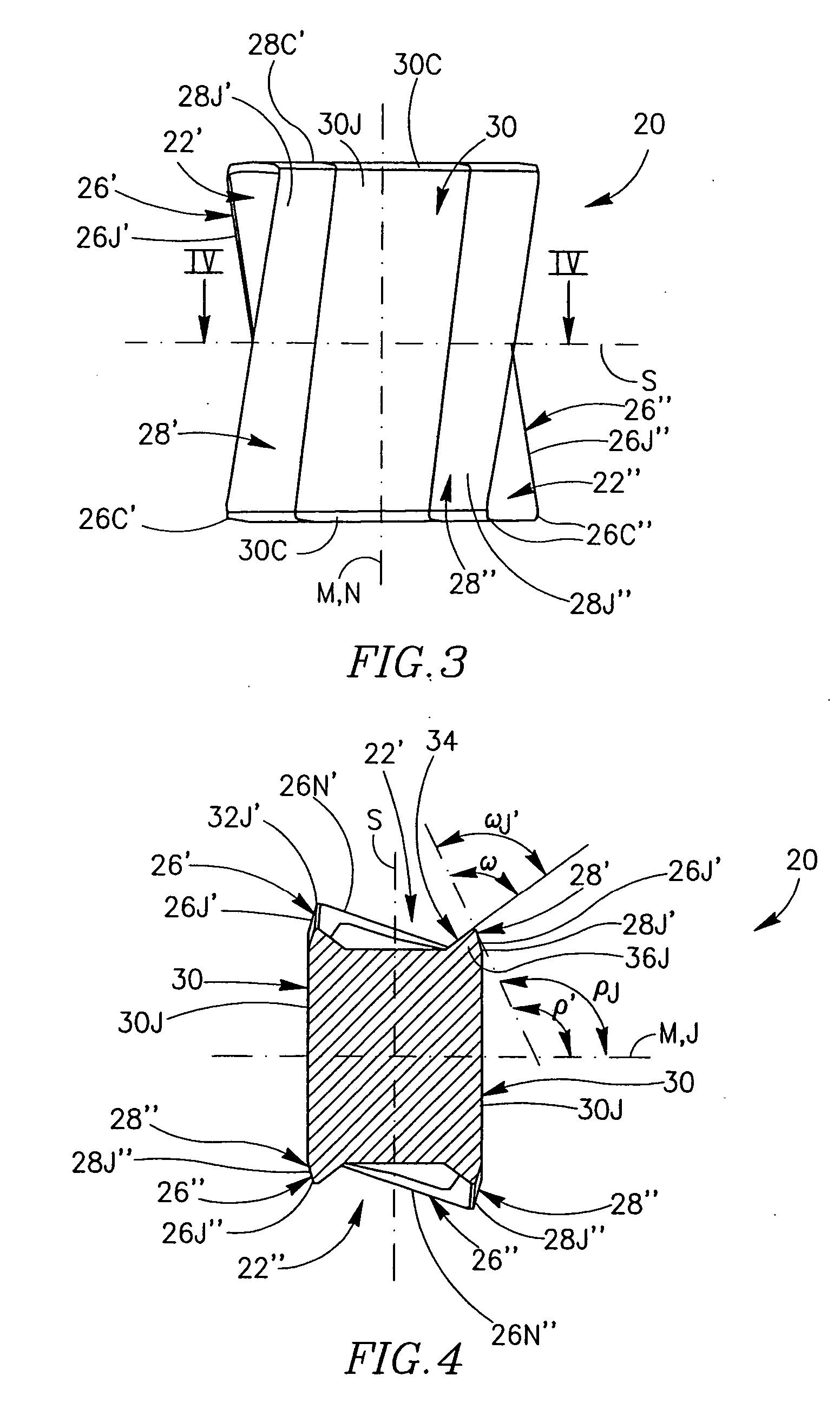
[0035] Attention is drawn to FIGS. 1 to 4. A pre-sintered green body 20 is preferably formed by compaction of a sinterable powder consisting of metallurgical, ceramic or cermet powder, and a binder. The green body 20 is generally rectangular in an end view and has identical, opposing (i.e., facing in opposite directions) top and bottom green body end faces 22′, 22″. In the present description, when following a reference numeral, a single prime (′) denotes a feature associated with the top side of the green body cutting insert, while a double prime (″) denotes a feature associated with the bottom side of the green body cutting insert. Each green body end face 22′, 22″ has a 180° rotational symmetry about an axis of symmetry S which passes through the two green body end faces 22′, 22″. A peripheral green body side surface 24 extends between the two green body end faces 22′, 22″. The peripheral green body side surface 24 comprises two opposing, identical major side faces 24J of a gener...


PUM

PropertyMeasurementUnit
relief angleaaaaaaaaaa
wedge angleaaaaaaaaaa
acute wedge angleaaaaaaaaaa

Abstract

A method for manufacturing a cutting insert green body having undercuts includes providing a die cavity formed in closed top and bottom dies; closing a bottom of the die cavity by a bottom punch accommodated in a punch tunnel formed in the bottom die; filling the die cavity with a pre-determined amount of sinterable powder; moving a top punch towards the die cavity through a punch tunnel formed in the top die; compacting the powder by urging the top and bottom punches towards each other, thereby forming the green body; and moving the top die and punch away from the bottom die and punch, thereby enabling removal of the formed green body. An apparatus for manufacturing a cutting insert green body having undercuts includes top and bottom dies which abut each other and top and bottom punches which slide in their respective dies.

Description

FIELD OF THE INVENTION [0001] The present invention relates to a method and apparatus for manufacturing pre-sintered cutting insert green bodies, to be subsequently sintered into cutting inserts. BACKGROUND OF THE INVENTION [0002] Fabrication of cutting inserts from sinterable powders, i.e., metallurgical, cermets or ceramics powders, comprises compaction of the sinterable powder, with or without a fugitive binder, into a pre-sintered green body, and subsequent sintering of the green body to produce a cutting insert. Compaction takes place under high pressures obtained through large opposing forces generated by top and bottom punches urged towards a die cavity formed in a die containing the sinterable powder, as is well known in the art. However, while parts having undercut elements may generally be pressed, the undercut elements inhibit release and subsequent extraction of the compacted green body from the die cavity. SUMMARY OF THE INVENTION [0003] In accordance with the present i...

Claims


Application Information

Patent Timeline
Patent Type & Authority Applications(United States)
IPC IPC(8): B22F3/00
CPCB22F3/03B22F2005/001B23C5/207B30B15/022B23C5/202B23C2200/284B30B15/02B30B11/00B23B27/16
Inventor SMILOVICI, CAROLATAR, OSAMABALLAS, ASSAFDAKWAR, BASEM
Owner ISCAR LTD
Learn More