Display system having a magnetic drive assembly and associated methods

Inactive Publication Date: 2006-08-03
AD4
View PDF14 Cites 6 Cited by
  • Summary
  • Abstract
  • Description
  • Claims
  • Application Information

AI Technical Summary

Benefits of technology

[0012] It is also an object of the present invention to provide a drive assembly having low maintenance needs. It is further an object of the invention to provide a display system that may be remotely operated.
[0015] The magnetic field may advantageously selectively cause rotation of the column members. Using a magnetic field to rotate the column members advantageously decreases maintenance costs of the display system. Further, the magnetic drive advantageously provides efficient rotation of the column members of the display system.
[0017] In other embodiments of the magnetic drive assembly, the energizing member may comprise a plurality of spaced-apart electromagnets in communication with one another, and positioned adjacent an outer periphery portion of the energizing member. Each of the plurality of electromagnets may be selectively, and individually, energized to form a magnetic field between a selective one of the electromagnets and the drive member. In such an embodiment, the electromagnets may be selectively and individually energized in series so that the magnetic field is a moving magnetic field that causes rotation of the column movement members. Similarly, the electromagnets may be selectively, and individually, energized in series to form a moving magnetic field between a selected one of the energized electromagnets and a selected one of the plurality of drive member. The plurality of drive members advantageously provides a stopping space to stop rotation of the column members at a predetermined position.
[0019] The magnetic drive assembly may further comprise a return cover connected to each column movement member to overlie the outer periphery of each energizing member. The return cover advantageously prevents collection of foreign matter between the energizing member and the column movement member. The return cover may comprise a plurality of lock members connected to a top portion thereof. Further, the display system may include a display base carried by the frame and having a plurality of lock member passageways formed therein. Accordingly, the lock members may selectively engage the lock member passageways to prevent rotation of the column members when the electromagnets are not energized. Accordingly, undesired rotation of the column members may advantageously be prevented.
[0024] In some embodiments of the display system, a wind sensor may be carried by the frame for sensing wind speed and wind direction. In such an embodiment, the wind sensor may comprise a remote transmitter for transmitting the predetermined signal to the receiver based on a predetermined wind speed and wind direction sensed by the wind sensor. The column members may be rotated to a position between any one of the first, second, third and forth positions responsive to the predetermined signal received from the remote transmitter of the wind sensor, i.e., forty-five degree rotation. This advantageously provides for additional stability for the display system when direct and high wind conditions exist.
[0025] Advertising indicia may be positioned on side portions of the column members. Accordingly, the display system of the present invention advantageously allows for enhanced display of advertising indicia, thereby enhancing advertising revenue on display systems.

Problems solved by technology

Unfortunately, however, billboards having triangularly shaped column members are limited to displaying three advertisements.
This type of display system, however, is limited to displaying only two different displays.

Method used


Image

  • Display system having a magnetic drive assembly and associated methods
  • Display system having a magnetic drive assembly and associated methods
  • Display system having a magnetic drive assembly and associated methods

Examples


Embodiment Construction

[0054] The present invention will now be described more fully hereinafter with reference to the accompanying drawings, in which preferred embodiments of the invention are shown. This invention may, however, be embodied in many different forms and should not be construed as limited to the embodiments set forth herein. Rather, these embodiments are provided so that this disclosure will be thorough and complete, and will fully convey the scope of the invention to those skilled in the art. Like numbers refer to like elements throughout, and multiple notation is used to indicate similar elements in alternate embodiments.

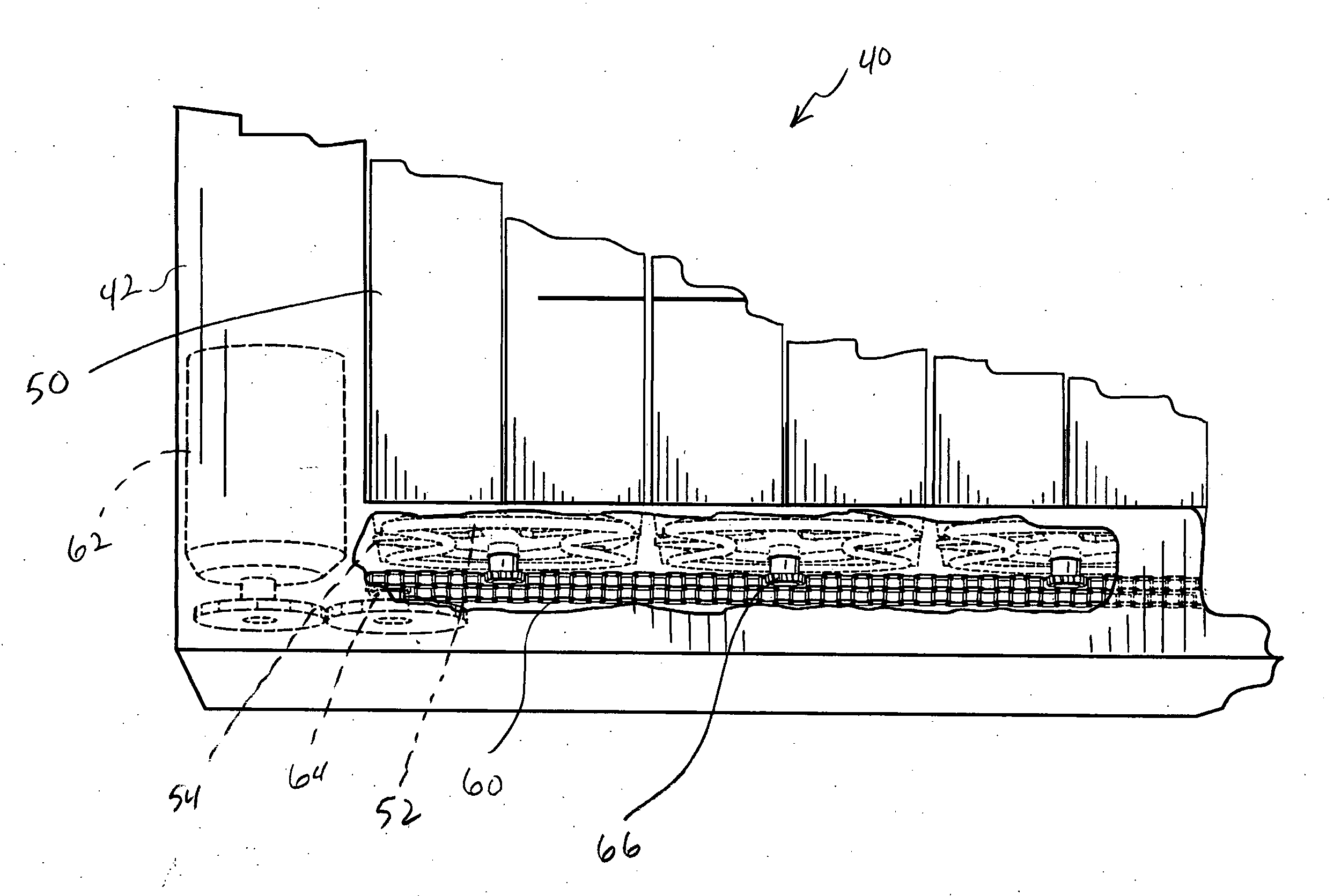
[0055] Referring initially to FIGS. 3 and 4A-4C, a display system 40 in accordance with the present invention is now described in detail. The display system 40 includes a frame 42, a plurality of column connection members 44 that are connected to the frame, and a plurality of four-sided column members 46 that are positioned adjacent one another and rotatably connected to...


PUM


Abstract

A display system may include a frame, column connection members connected to the frame, and column members rotatably connected to the column connection members. The display system may also include a magnetic drive assembly carried by the frame that engages the column connection members to selectively rotate the column members. The magnetic drive assembly may include a power source, energizing members connected to the power source, and column movement members connected to the column connection members. The energizing members may include an electromagnet, and the column movement members may be positioned spaced-apart from and overlying the energizing members. The electromagnet of the energizing members may be selectively energized to form a magnetic field between the energizing members and the column movement members to selectively cause rotation of the column members.

Description

RELATED APPLICATIONS [0001] This application is related to U.S. patent application Ser. No. ______, titled Display System And Associated Methods, filed simultaneously herewith, by the inventors of the present application, the contents of which are incorporated herein by reference.FIELD OF THE INVENTION [0002] The present invention relates to the field of advertising and, more particularly, to field of rotating billboards, and related methods. BACKGROUND OF THE INVENTION [0003] As illustrated in FIGS. 1 and 2A-2C, rotating signs 30 are well known in the advertising industry. More particularly, rotating billboards typically include a plurality of rotating column members 32. These column members 32 typically have a triangular shape so that they may be positioned adjacent one another and simultaneously rotated without interference from one another. More particularly, the column members 32 may be moved between first, second and third positions. FIG. 2A illustrated a column member 32 posi...

Claims


Application Information

Patent Timeline
IPC IPC(8): G09F11/02
CPCG09F11/025
Inventor LYONS, JAMES P.MACGEORGE, MICHAEL W.REYNOLDS, JOHN NORTON IV
Owner AD4
Why Eureka
Try Eureka