Multi-cyclone dust separating apparatus

a technology of dust separating apparatus and multi-cyclone, which is applied in the direction of filtration separation, cleaning filter means, separation processes, etc., can solve the problems of inability to separate out fine dust particles, affecting the ability to separate out minute dirt particles, and extra ducting, etc., to achieve the effect of reducing the structure of the multi-cyclone dust separating apparatus, reducing the cost of filtration and cleaning, and improving the efficiency of filtration

Inactive Publication Date: 2006-08-03
SAMSUNG GWANGJU ELECTRONICS CO LTD
View PDF5 Cites 205 Cited by
  • Summary
  • Abstract
  • Description
  • Claims
  • Application Information

AI Technical Summary

Problems solved by technology

One problem with cyclone dust separators is their relative inability to separate out fine dust particles.
Although multi-cyclone dust separating devices provide better dirt particle separation than conventional cyclone dust separating devices, their ability to separate out minute dirt particles is compromised by the geometry required to route dust laden air through a primary cyclone and then into one or more secondary cyclones.
Among other things, extra ducting makes the structure of the multi-cyclon...

Method used


Image

  • Multi-cyclone dust separating apparatus
  • Multi-cyclone dust separating apparatus
  • Multi-cyclone dust separating apparatus

Examples


Embodiment Construction

[0019] Hereinafter, a multi-cyclone dust separating apparatus according to a non-limiting embodiment of the present invention will now be described in greater detail with reference to the accompanying drawings.

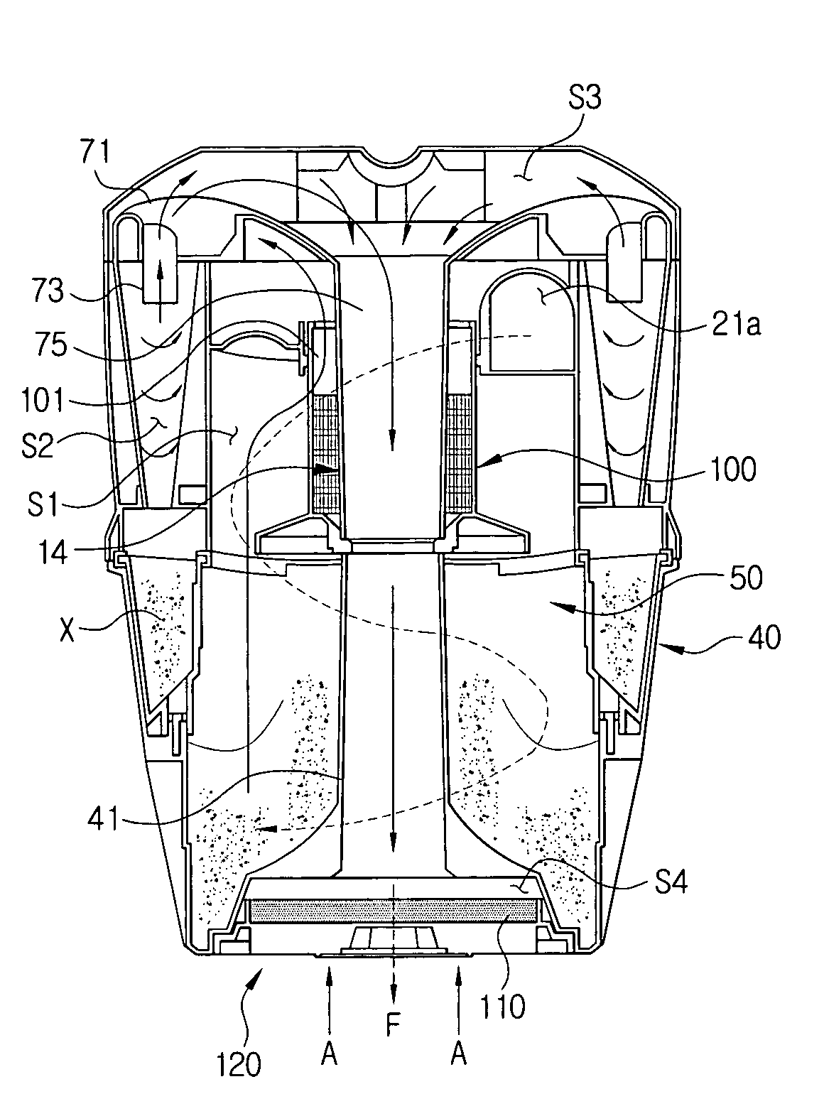
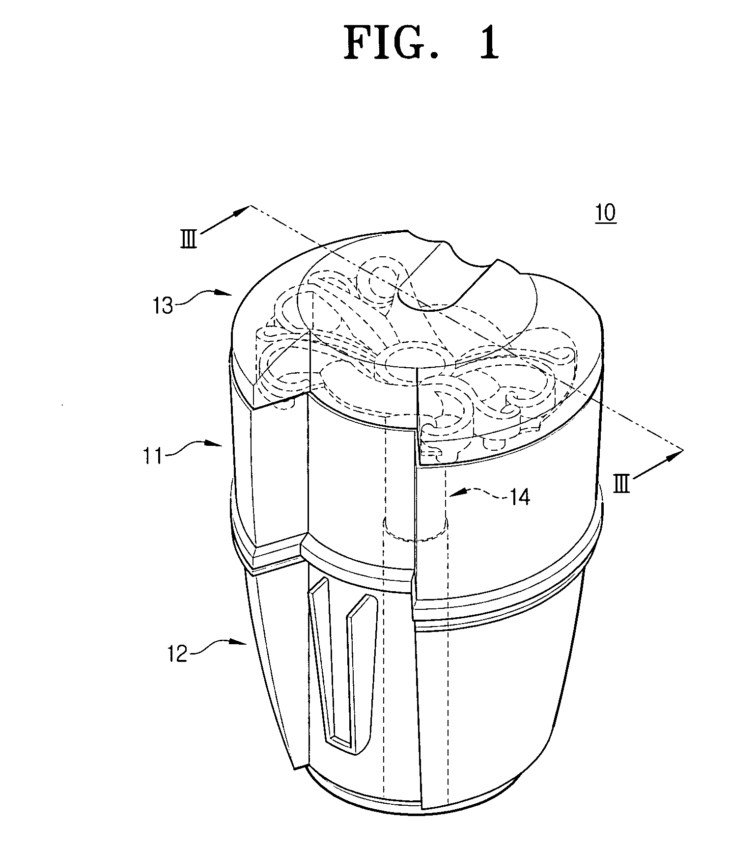
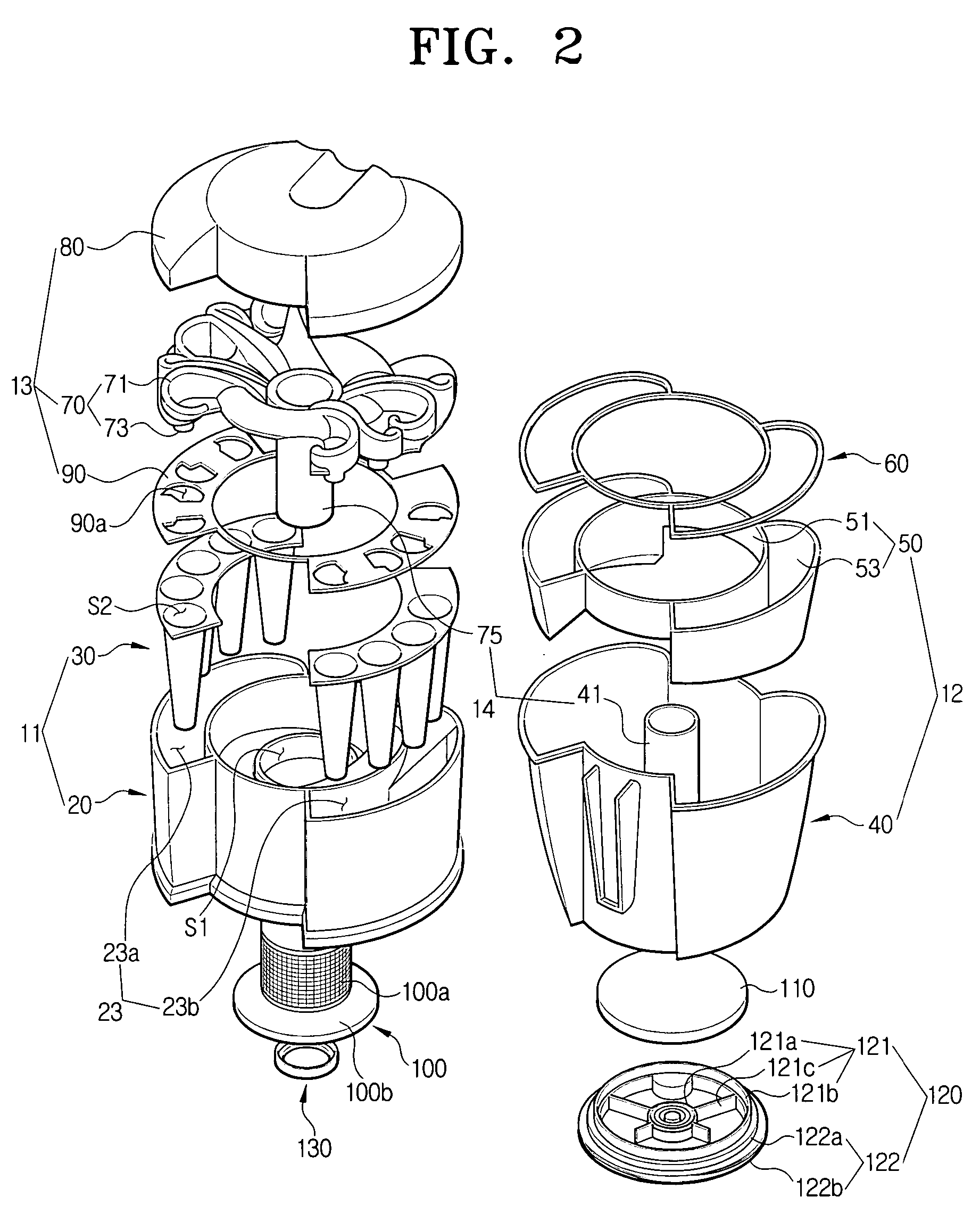
[0020] Referring to FIG. 1, a multi-cyclone dust separating apparatus 10 includes a multi-cyclone unit 11, a dirt (and / or debris) collecting unit 12, a cover unit 13 and an air discharge duct 14. In FIG. 2, the multi-cyclone unit 11 includes a first cyclone chamber body 20 and a plurality of secondary cyclone chamber bodies 30 to centrifugally separate dirt from drawn-in air. The first cyclone chamber body 20 includes a first cyclone chamber S1 formed in a center portion thereof and a protection chamber 23 formed along a circumference of the wall of the first cyclone chamber S1 in a non-connecting manner such that the secondary cyclone chamber bodies 30 are separate structures.

[0021] The first cyclone chamber S1 has an air suction port 21a (see FIG. 3) formed on a side of th...


PUM

PropertyMeasurementUnit
Timeaaaaaaaaaa
Circumferenceaaaaaaaaaa

Abstract

A multi-cyclone dust separating apparatus includes: a multi-cyclone unit including a first cyclone chamber body having a first cyclone chamber and at least one protection chamber formed around at least a portion of an outer circumference of the first cyclone chamber, and at least one secondary cyclone chamber body disposed in the protection chamber, each secondary cyclone chamber body having at least one secondary cyclone chamber; a cover unit connecting an upper end of the multi-cyclone unit and guiding air discharged from the first cyclone chamber to the at least one secondary cyclone chamber; a dirt collecting unit adapted to connect to a lower end of the multi-cyclone unit and configured to collect dirt separated from the air in the first and secondary cyclone chambers; and an air discharge duct configured to discharge air that has passed through the multi-cyclone unit.

Description

CROSS-REFERENCE TO RELATED APPLICATIONS [0001] This application claims the benefit of priority under 35 U.S.C. § 119 to Korean Patent Application No. 2005-08585, filed on Jan. 31, 2005 and Korean Patent Application No. 2005-27927, filed on Apr. 4, 2005, the contents of each of which are incorporated herein by reference. This application may also be related to commonly owned U.S. patent application Ser. No. 10 / 840,248, filed May 7, 2004; commonly owned U.S. patent application Ser. No. 10 / 840,230, filed May 7, 2004; commonly owned U.S. patent application Ser. No. 10 / 840,231, filed May 7, 2004; commonly owned U.S. patent application Ser. No. 10 / 840,229, filed May 7, 2004; commonly owned U.S. patent application Ser. No. 10 / 832,346, filed Apr. 27, 2004; commonly owned U.S. patent application Ser. No. 10 / 851,114, filed May 24, 2004; commonly owned U.S. patent application Ser. No. 10 / 847,593, filed May 18, 2004; commonly owned U.S. patent application Ser. No. 10 / 847,257, filed Jun. 24, 200...

Claims


Application Information

Patent Timeline
IPC IPC(8): B01D45/12
CPCA47L9/122A47L9/1625A47L9/1641A47L9/1666A47L9/1683Y10S55/03
Inventor LEE, DONG-YUNGWEUN, OH-GYUYOO, DONG-HUN
Owner SAMSUNG GWANGJU ELECTRONICS CO LTD
Why Eureka
Try Eureka