Cold climate air-source heat pump

a heat pump and cold climate technology, applied in heat pumps, lighting and heating apparatuses, refrigeration components, etc., can solve the problem of increasing the temperature of refrigerant fluid to potentially unsafe levels

Inactive Publication Date: 2006-08-03
NYLE SYST
View PDF8 Cites 10 Cited by
  • Summary
  • Abstract
  • Description
  • Claims
  • Application Information

AI Technical Summary

Problems solved by technology

When a defrosting cycle is used, the temperature of the refrigerant fluid may be increased to potentially unsafe levels.

Method used


Image

  • Cold climate air-source heat pump
  • Cold climate air-source heat pump
  • Cold climate air-source heat pump

Examples


Embodiment Construction

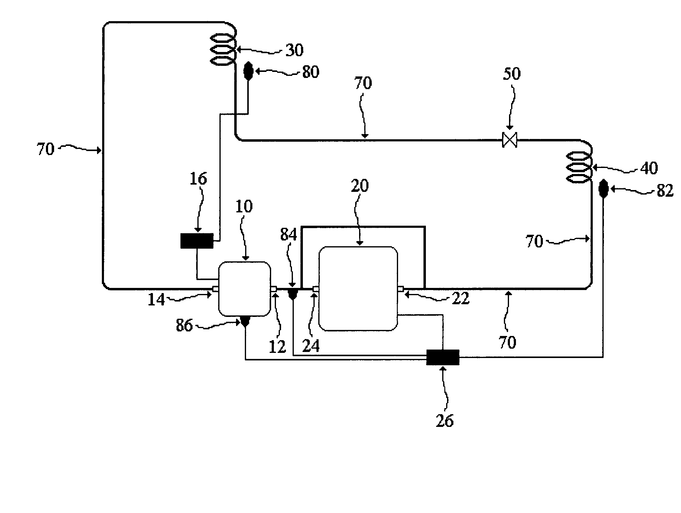
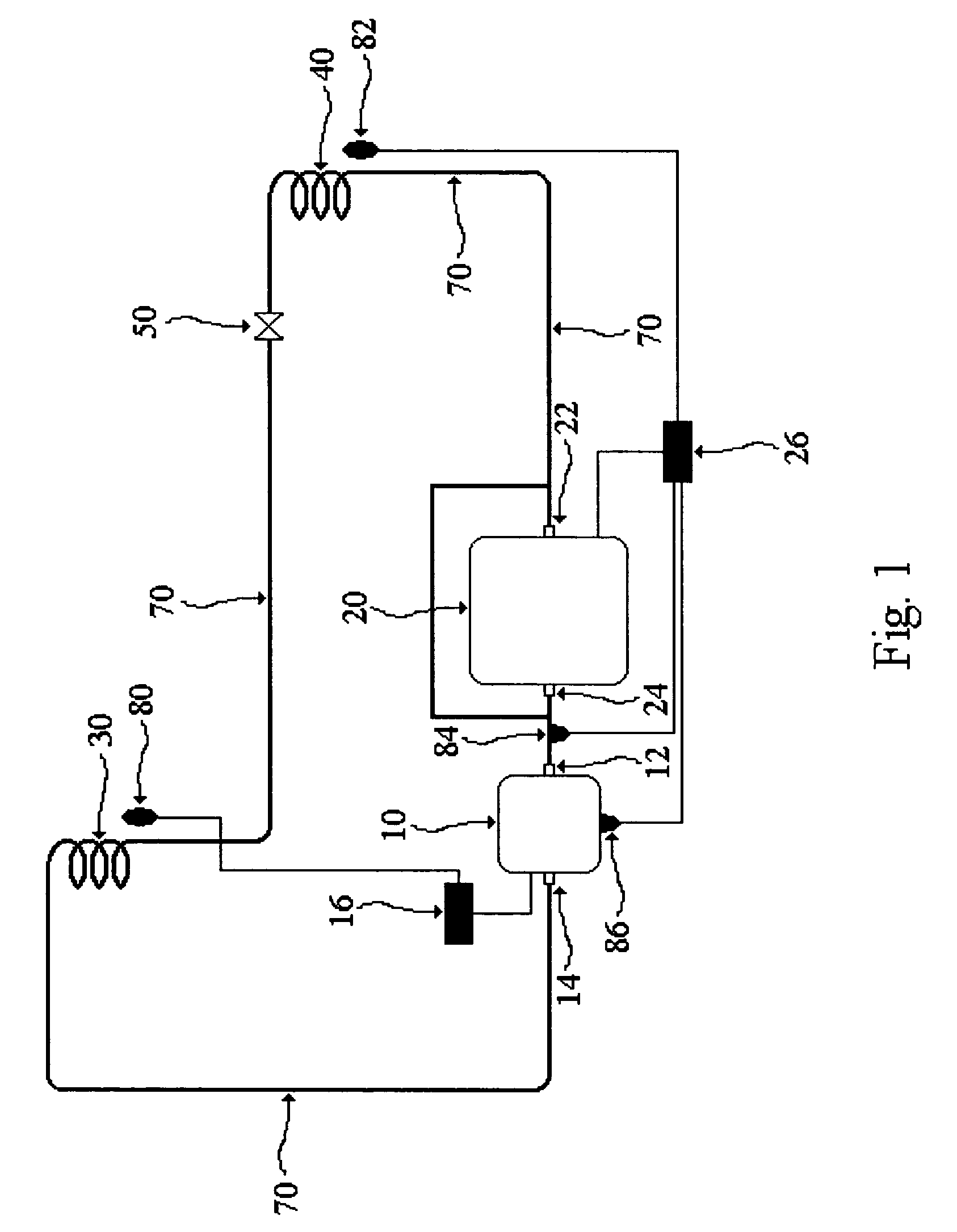
[0023] The present invention is an improvement on known air-source heat pumps using a booster compressor along with a primary compressor for efficient operation in cold weather climates. The basic components of the invention are depicted in FIG. 1, a schematic drawing of the interrelationship of those components. These include a primary compressor 10, a booster compressor 20, a first heat exchanger 30, a second heat exchanger 40, an expansion device 50, flow conduit means 70, a first sensor means 80 for sensing the temperature of the internal ambient air, a second sensor means 82 for sensing the temperature of the external ambient air, a third sensor means 84 for sensing the temperature of refrigerant fluid flowing between the booster compressor 20 and the primary compressor 10, a fourth sensor means 86 for sensing the operative state of the primary compressor 10, a primary compressor operation control means 16 responsive to inputs from the first sensor means 80, and a booster compr...


PUM


Abstract

An improved cold climate air-source heat pump comprising at least a primary compressor, a booster compressor, a first heat exchanger associated with an indoor environment and a second heat exchanger associated with an outdoor environment and with one heat exchanger acting as an evaporator and the other heat exchanger acting as a condenser, an expansion device, flow conduit means for circulating a refrigerant fluid in a closed loop, a first sensor means for sensing the temperature of the internal ambient air, a second sensor means for sensing the temperature of the external ambient air, a third sensor means for sensing the temperature of the refrigerant fluid flowing between the booster compressor and the primary compressor, a fourth sensor means for sensing the operative state of the primary compressor, a primary compressor operation control means responsive to inputs from the first sensor means, and a booster compressor operation control means responsive to inputs from the second, third, and fourth sensor means. The booster compressor operation control means is configured to initiate and shut down operation of the booster compressor based on inputs from the various sensor means, to ensure safe operation of the system and improved durability of the air-source heart pump.

Description

FIELD OF THE INVENTION [0001] The invention relates to environmental climate control devices, namely, air-source heat pumps. Specifically, this invention relates to an improvement on cold weather air-source heat pumps for residential and commercial use wherein the durability and safety of operation of said heat pumps is increased. BACKGROUND OF THE INVENTION [0002] Air-source heat pumps are well known in the art. See, e.g., U.S. Pat. No. 6,615,602 (Wilkinson), which describes a typical air-source heat pump in detail. Air-source heat pumps incorporate a combination of compressors and condensers in a closed-loop system to draw heat energy from the outside air for use in heating interior spaces. They can also be used in reverse to provide for air conditioning of interior spaces. Air-source heat pumps rely on well-known principles of thermodynamics to extract energy from a given volume of air. The maximum energy that can be extracted from a given volume of air by an air-source heat pump...

Claims


Application Information

Patent Timeline
Patent Type & Authority Applications(United States)
IPC IPC(8): F25B5/00F25B7/00F25B1/00F25B49/00F25B1/10
CPCF25B1/10F25B30/02F25B2400/0401F25B2600/2507F25B2700/2104F25B2700/2106F25B2700/21152
Inventor LEWIS, DONALD
Owner NYLE SYST
Why Eureka
Try Eureka