Hyperbaric therapy capsule

a capsule and hyperbaric technology, applied in the field of hyperbaric therapy capsules, can solve the problems of inability to provide for users or patients, inability to use the capsule at home, and inability to meet the needs of users or patients,

Inactive Publication Date: 2006-08-03
OXYGEN THERAPY INT
View PDF22 Cites 26 Cited by
  • Summary
  • Abstract
  • Description
  • Claims
  • Application Information

AI Technical Summary

Benefits of technology

The patent text describes a capsule for single-person use that has controls and indicators for pressure, temperature, and air/O2 flow. The controls and indicators are located on the base of the capsule or on the lower part of the canopy. The capsule can also have audible and visual alarms, such as a power-failure alarm, an excess temperature alarm, and an excess CO2 alarm. These indicators can be duplicated on the exterior of the capsule. The activation of any alarm can automatically depressurize the capsule and even release the canopy. A standby pressure vessel or electric battery may be needed to perform these functions even if there is no mains power.

Problems solved by technology

The technical problem addressed in this patent is the lack of hyperbaric chambers that are suitable for home use by individuals without assistance and that allow the user to open the chamber from within without needing assistance. Current hyperbaric chambers are large, complex, and require the presence of expert staff to operate them. Additionally, they are designed to be used in a hospital or clinical environment and cannot be easily transported to a diver or athlete for training purposes.

Method used


Image

  • Hyperbaric therapy capsule
  • Hyperbaric therapy capsule
  • Hyperbaric therapy capsule

Examples


Embodiment Construction

[0018] Having portrayed the nature of the present invention, a particular example will now be described with reference to the accompanying drawings. However, those skilled in the art will appreciate that many variations and modifications can be made to the example, and many other examples can be devised, without departing from the scope of the invention as outlined above. In the accompanying drawings:

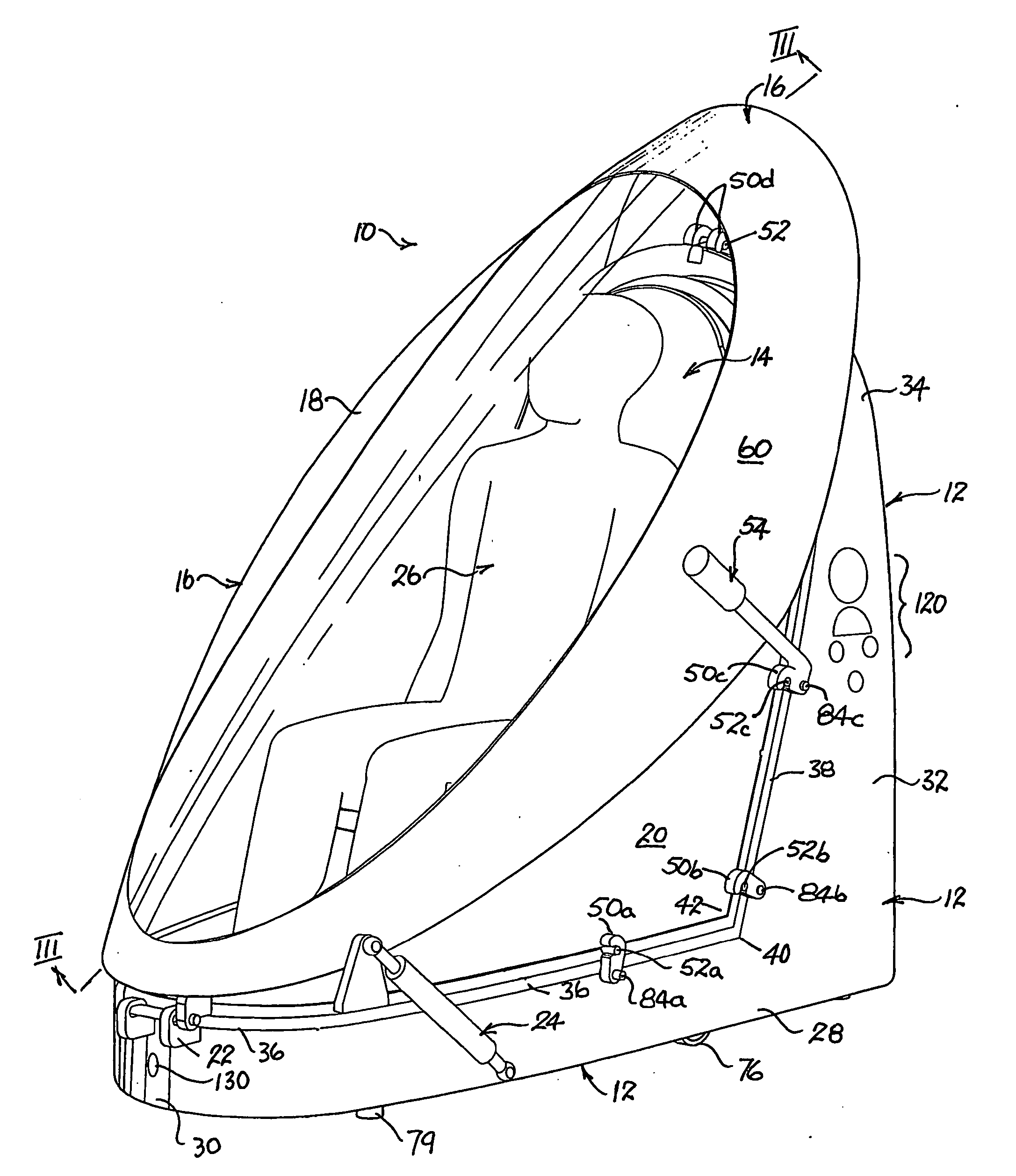
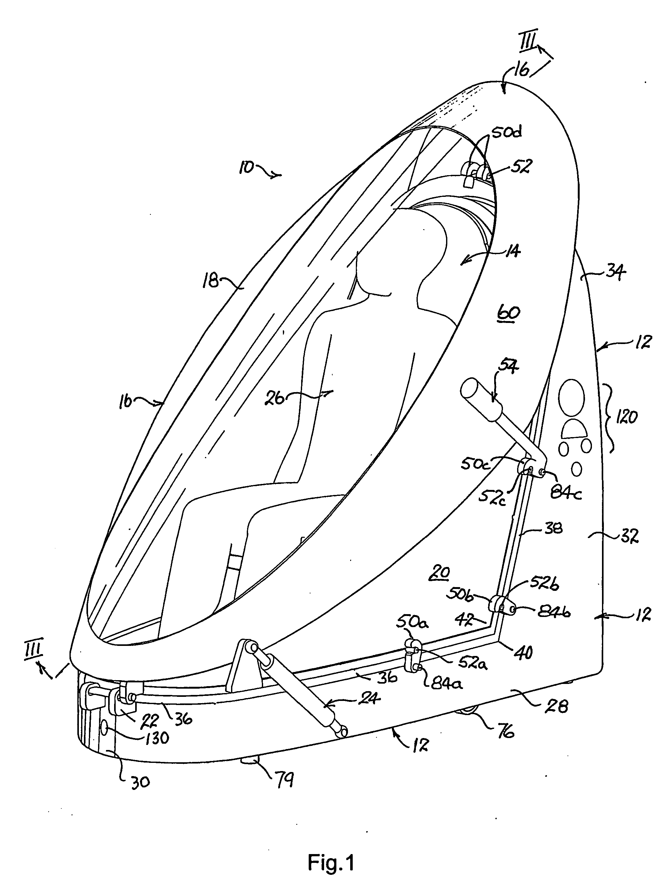
[0019]FIG. 1 is a perspective view of the capsule of the chosen example with the canopy closed and a user seating inside.

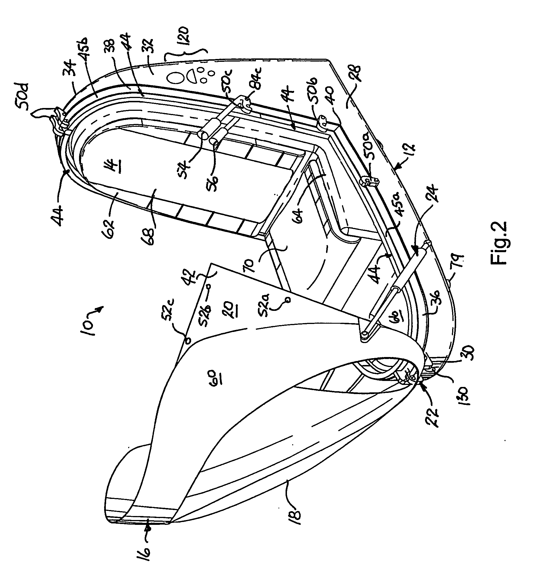
[0020]FIG. 2 is a perspective view of the capsule of FIG. 1 with the canopy open and no user visible.

[0021]FIG. 3 is a longitudinal cross-section of the closed capsule taken on plane III-III of FIG. 1, the user not being shown.

[0022]FIG. 4A is a perspective view of the underside of base and canopy frames with the canopy frame in the closed position, showing the manner in which the multiple latches are operated in unison.

[0023]FIG. 4B is a side elevation of the ba...


PUM


Abstract

A hyperbaric capsule (10) has a base (12) forming a seat (14) that can be enclosed by an elongate oval canopy (16) having a large transparent window (18) formed therein. The bottom of the front of the canopy (16) is pivotally attached to the front of the base (12) by a hinge assembly (22) and can be locked in the closed position on the base by a plurality of latches (50a-50d) that are conjointly operated by an external lever (54) and an internal lever (56, not shown in FIG. 1). The weight of the canopy upon opening is borne by a pair of side gas or spring struts (24).

Description


Claims


Application Information

Patent Timeline
Owner OXYGEN THERAPY INT
Why Eureka
Try Eureka