Heat exchanger

a technology of heat exchanger and fin, which is applied in the direction of tubular elements, lighting and heating apparatus, stationary conduit assemblies, etc., can solve the problems of inability to introduce cooling air to the inter-louver path, inability to improve inability to easily catch cooling air by the louver wall surface, etc., to achieve the effect of improving the heat transfer rate of the fin, shortening the louver width, and improving the performan

Inactive Publication Date: 2006-08-03
DENSO CORP
View PDF10 Cites 9 Cited by
  • Summary
  • Abstract
  • Description
  • Claims
  • Application Information

AI Technical Summary

Benefits of technology

[0006] In view of the above-mentioned fact, the object of this invention is to provide a heat exchanger in which the cooling air can be easily caught by the louver wall surfaces even with a shorter louver width.
[0008] With this configuration, the louver pitch height HLP in real terms is increased and, even when the louver width is shortened, the cooling air can be caught by the louver wall surfaces. Therefore, the cooling air can be positively introduced to the inter-louver path, and the heat transfer rate of the fins can be improved.
[0011] With this configuration, the real louver pitch height HLP is increased, and even when the louver width is shortened, the cooling air can be caught by the louver wall surfaces. Thus, the cooling air can be positively introduced to the inter-louver path for an improved heat transfer rate of the fins.
[0014] With this configuration, the real louver pitch height HLP is increased and, even when the louver width is shortened, the cooling air can be caught by the louver wall surfaces. Thus, the cooling air can be positively introduced to the inter-louver path for an improved heat transfer rate of the fins.

Problems solved by technology

In the conventional heat exchanger described above, shortening of the louver width to improve the performance reduces the louver pitch height (the size of the louver wall surface in the cooling water flow direction X1), and therefore the cooling air cannot be easily caught by the louver wall surfaces.
As a result, the cooling air cannot be introduced to the inter-louver path.
In spite of an improved effect at the forward end, the heat transfer rate of the fins cannot be improved.

Method used


Image

  • Heat exchanger
  • Heat exchanger
  • Heat exchanger

Examples


Embodiment Construction

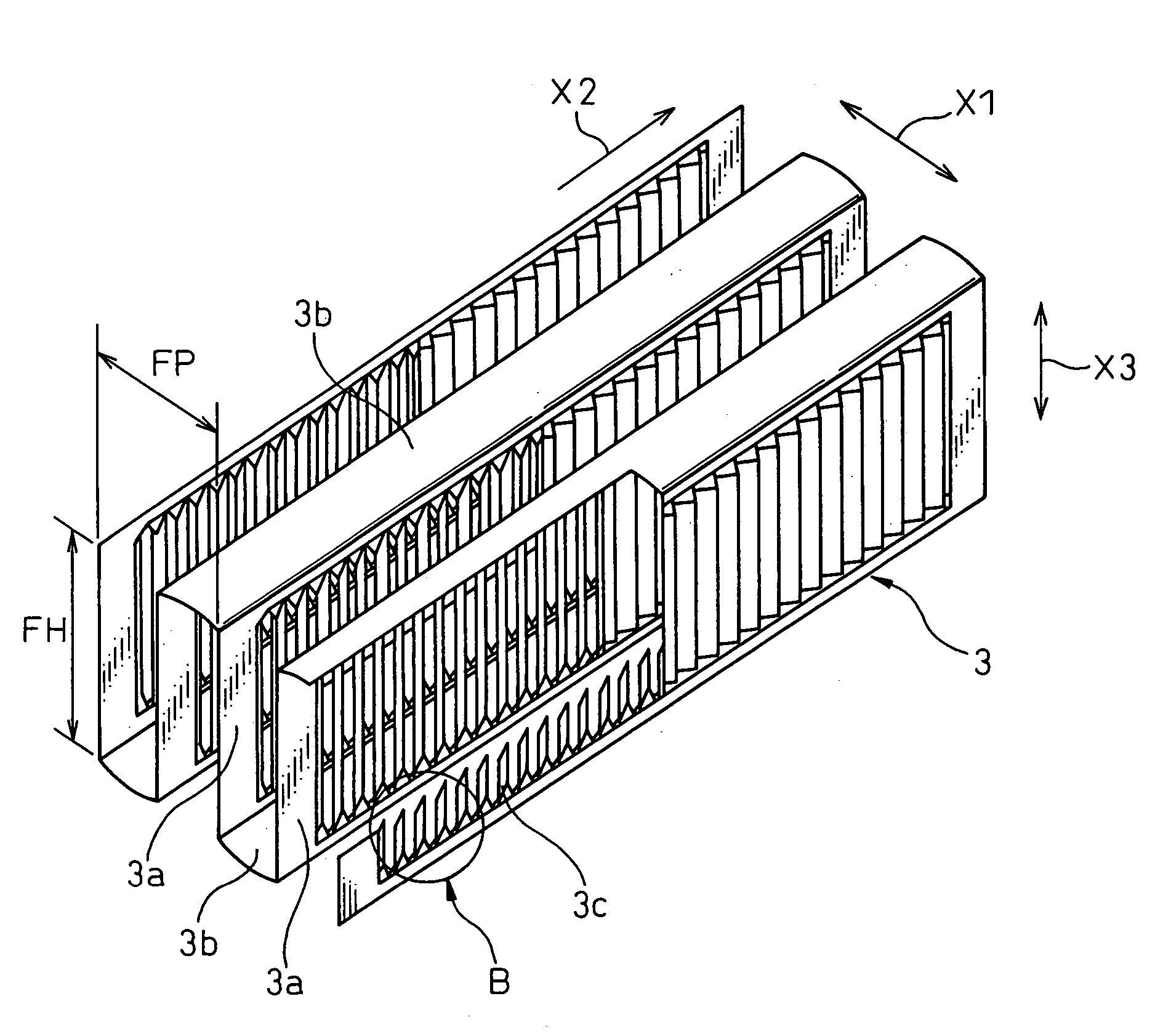
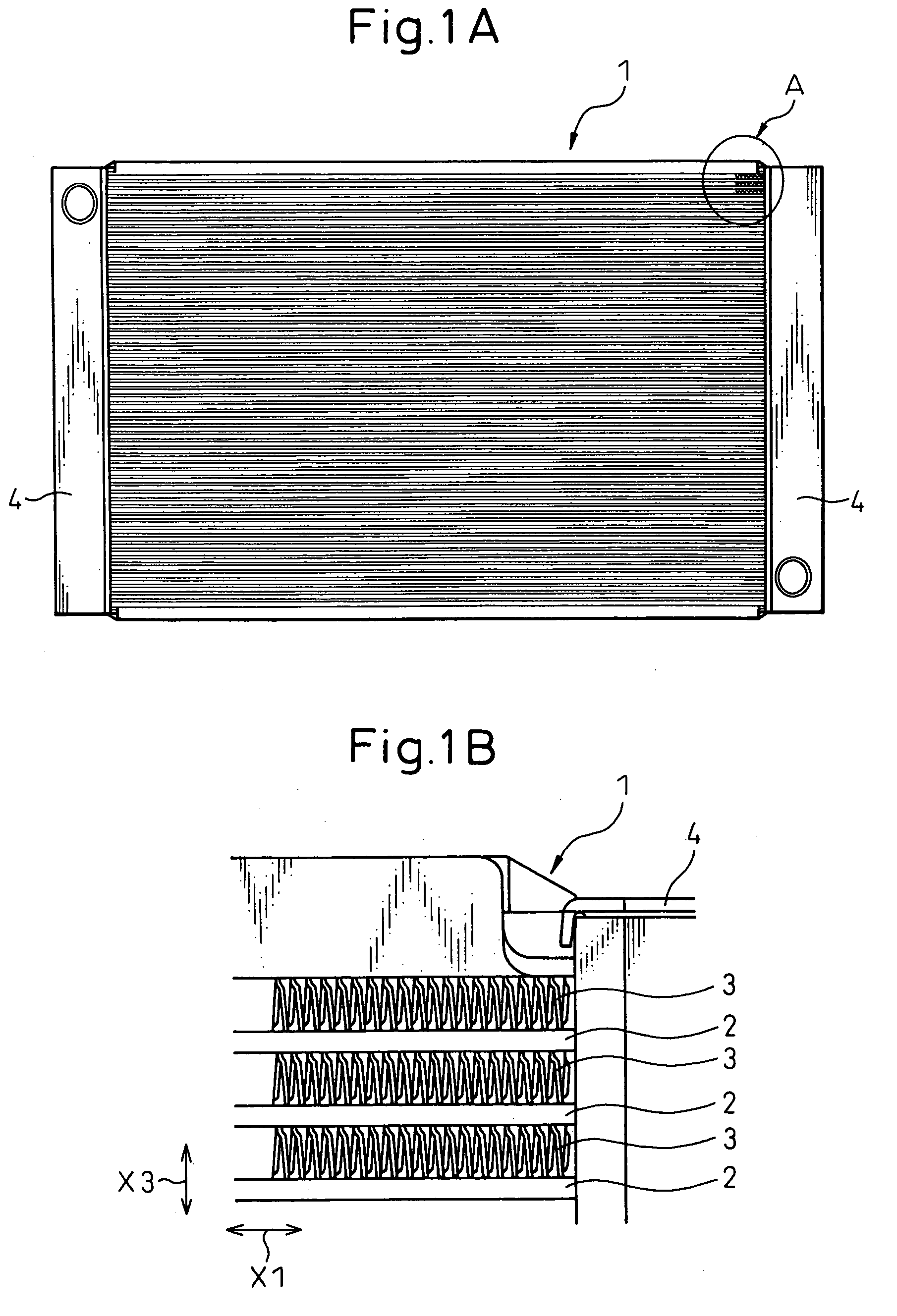
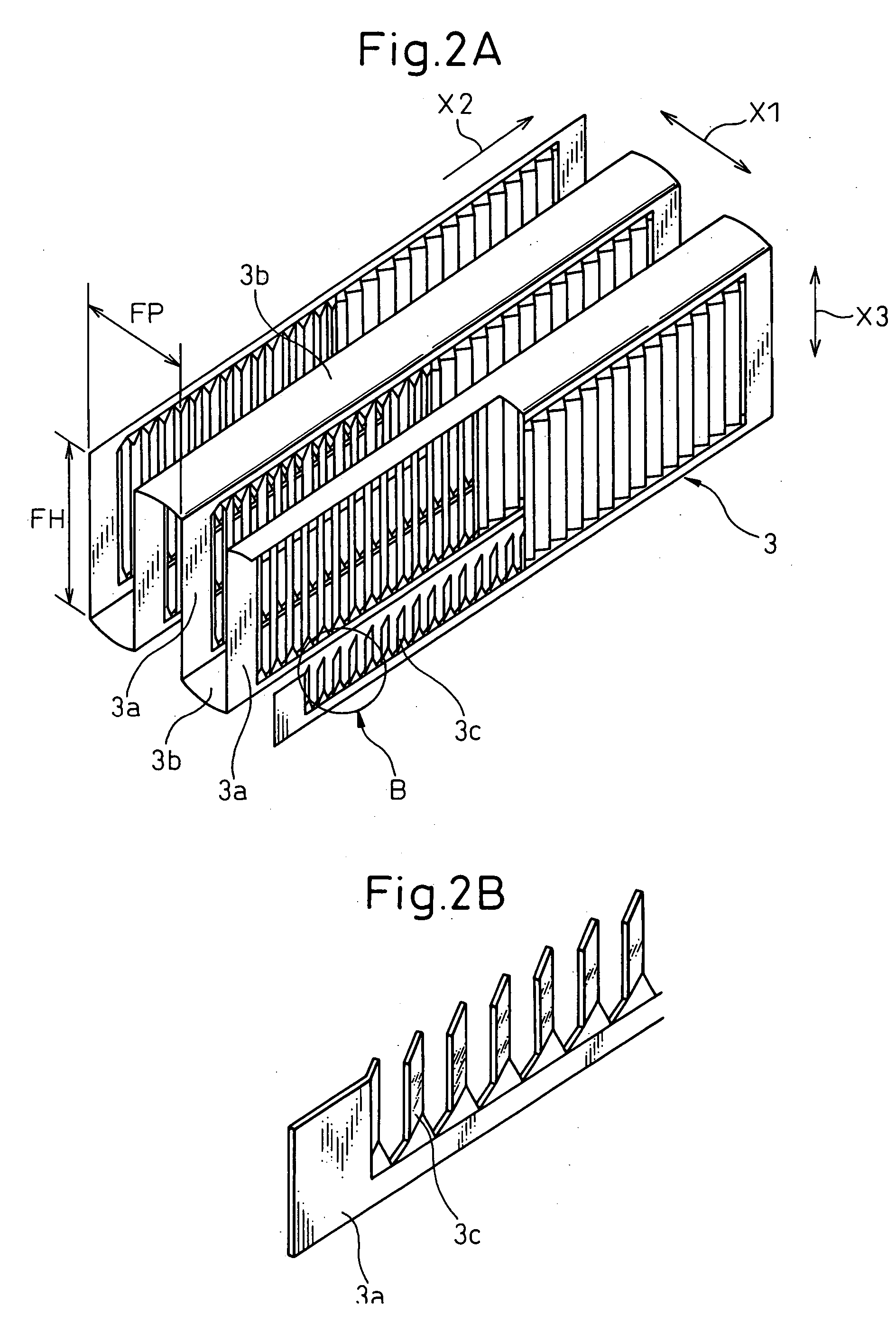
[0029] A heat exchanger according to a first embodiment of the invention is used as a radiator for cooling the cooling water of a vehicle engine (internal combustion engine) by exchanging heat between the cooling water and the air. FIG. 1A is a front view of a heat exchanger according to a first embodiment of the invention. FIG. 1B is an enlarged view of a portion A in FIG. 1A. FIG. 2A is a partly cutaway perspective view of fins 3 shown in FIG. 1. FIG. 2B is an enlarged view of a portion B shown in FIG. 2A. FIG. 3 is a perspective view of the fins 3 of FIG. 1B as seen in a direction different from FIG. 2A. FIG. 4 is a side view of the fins 3 of FIG. 1B seen from the direction X3 along the fin height. FIG. 5 is a sectional view of the fins 3 of FIG. 1B seen from the direction X3 along the fin height. FIG. 6A is a sectional view schematically showing the fins 3 of FIG. 1B as seen from the direction X3 along the fin height. FIG. 6B is an enlarged view of a portion C in FIG. 6A.

[0030]...


PUM


Abstract

A heat exchanger, in which louver wall surfaces (3c) are twisted at a predetermined angle (θ1) with respect to a plurality of flat portions (3a) of fins (3) and an inter-louver path (5) is formed between the adjacent louver wall surfaces (3c), is disclosed. The center points (3d) of some louver wall surfaces (31c) are displaced from the center points (3d) of the other louver wall surfaces (32c) along the cooling water flow direction (X1). As a result, the real louver pitch height (HLP) is increased beyond the louver pitch heights (HLP1, HLP2) of the louver wall surfaces (31c, 32c), respectively. Even in the case where the louver width (L) is reduced, therefore, the cooling air can be caught by the louver wall surfaces (3c).

Description

BACKGROUND OF THE INVENTION [0001] 1. Field of the Invention [0002] This invention relates to a heat exchanger effectively applicable to a radiator for exchanging heat between the cooling water of an internal combustion engine and the air. [0003] 2. Description of the Related Art [0004] In a conventional heat exchanger, the fins have louver wall surfaces of which the forward end effectively improves the heat transfer rate. By tilting the louver wall surfaces, at a predetermined angle to flat portions, the cooling air flow is changed and introduced to a path between adjacent louver wall surfaces (inter-louver path), thereby improving the heat transfer rate of the fins (Japanese Unexamined Patent Publication No. 2003-83690). SUMMARY OF THE INVENTION [0005] In the conventional heat exchanger described above, shortening of the louver width to improve the performance reduces the louver pitch height (the size of the louver wall surface in the cooling water flow direction X1), and therefor...

Claims


Application Information

Patent Timeline
Patent Type & Authority Applications(United States)
IPC IPC(8): F28D1/02
CPCF28F1/128
Inventor OZAKI, TATSUO
Owner DENSO CORP
Why Eureka
Try Eureka