
Barrier crossover device

a crossover device and barrier technology, applied in ladders, construction, building construction, etc., can solve the problems of deterioration or breakdown of structures, inability to easily move or transfer, and exposure to elements, and achieve the effect of convenient and rapid transportation of devices

Inactive Publication Date: 2006-08-03
PHILLIPS ALEXANDER K +1
View PDF31 Cites 16 Cited by
  • Summary
  • Abstract
  • Description
  • Claims
  • Application Information

AI Technical Summary

Benefits of technology

[0026] Accordingly, an advantage of the present invention is to provide a barrier crossover device which enables a user to easily and quickly transport the device, set up the device and crossover a barrier at a remote location.
[0027] Another advantage of the present invention is to provide a barrier crossover device which enables a user to adjust the angle between opposing sides of the device to adjust the device for different barrier widths.
[0028] A further advantage of the present invention is to provide a barrier crossover device which enables a user to adjust the height of the device to accommodate for different terrains and barrier heights.
[0029] Another advantage of the present invention is to provide a barrier crossover device which includes a removable platform which supports the weight of at least one user and enables a user to crossover from one side of the device to the other side of the device.
[0030] Additional features and advantages of the present invention are described in, and will be apparent from, the following

Problems solved by technology

These structures are semi-permanent structures which can not be easily moved or transferred from one location to the next.
Because these structures are not easily movable to a covered storage area such as a barn, garage or shed, these structures are exposed to the elements and deteriorate or breakdown over time.

Method used


Image

  • Barrier crossover device
  • Barrier crossover device
  • Barrier crossover device

Examples


Embodiment Construction

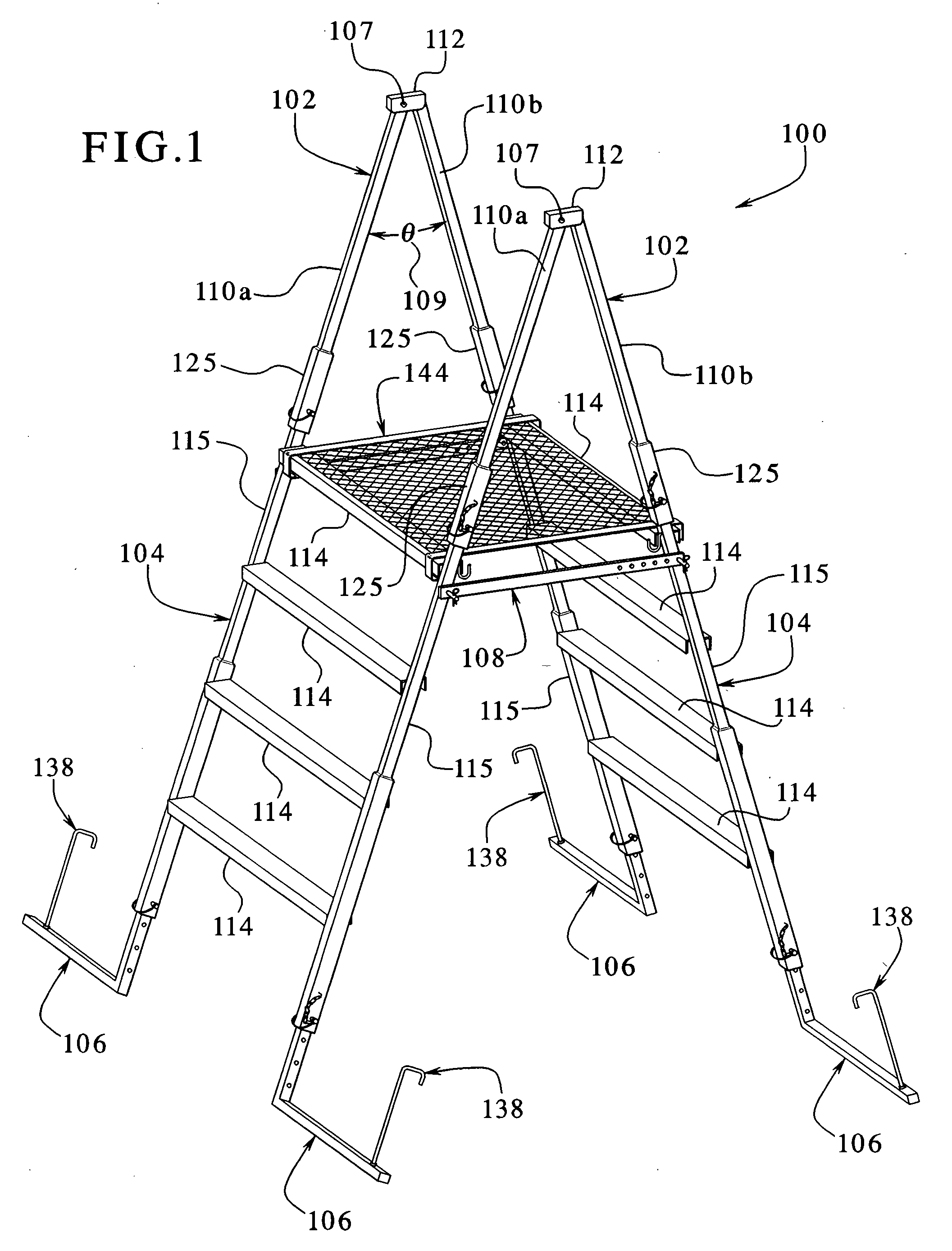
[0040] The present invention is directed to a barrier crossover device and more specifically to a portable, foldable or collapsible crossover device which can be disassembled, easily transported and quickly setup at remote locations to enable a user to crossover a barrier such as a fence or wall.

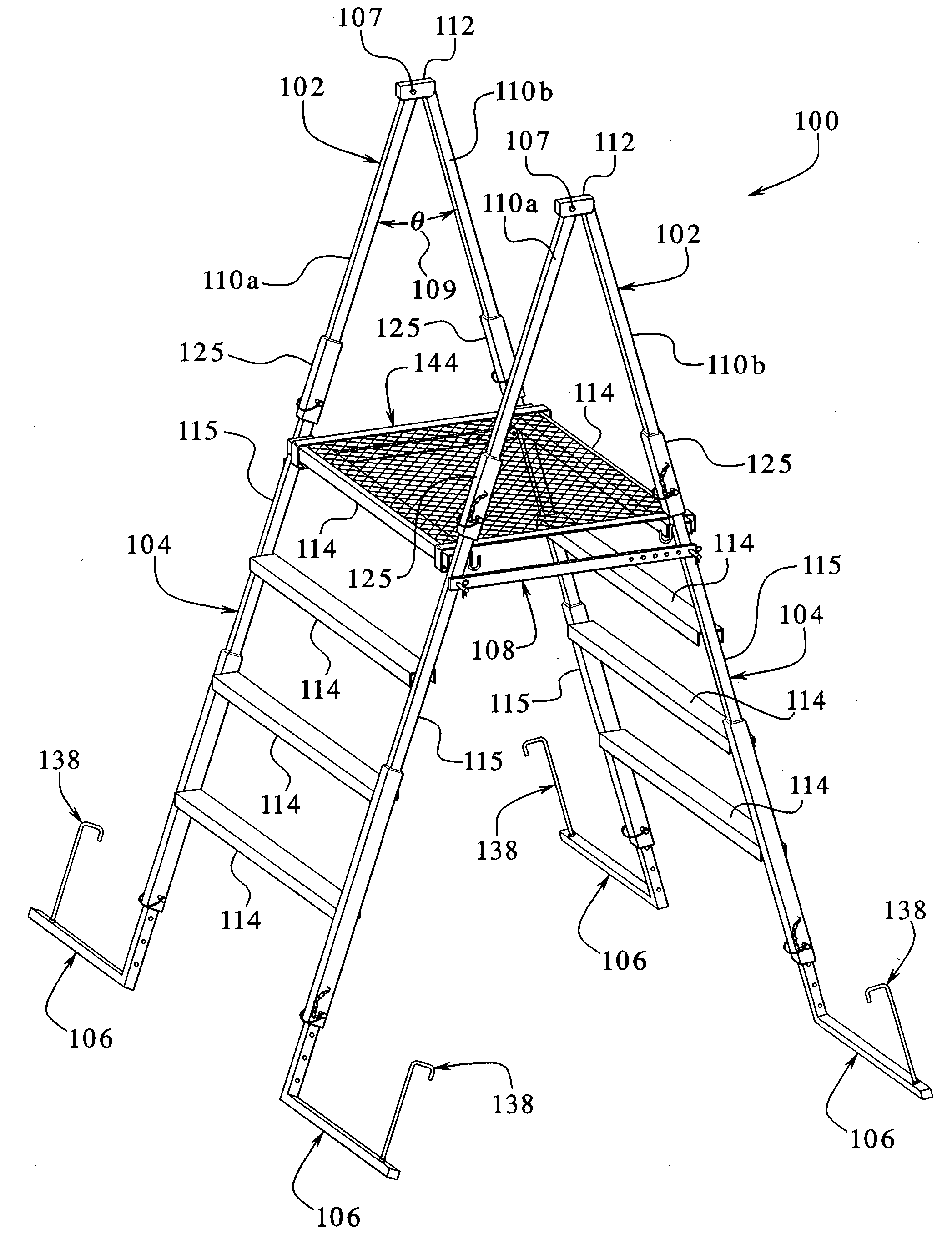
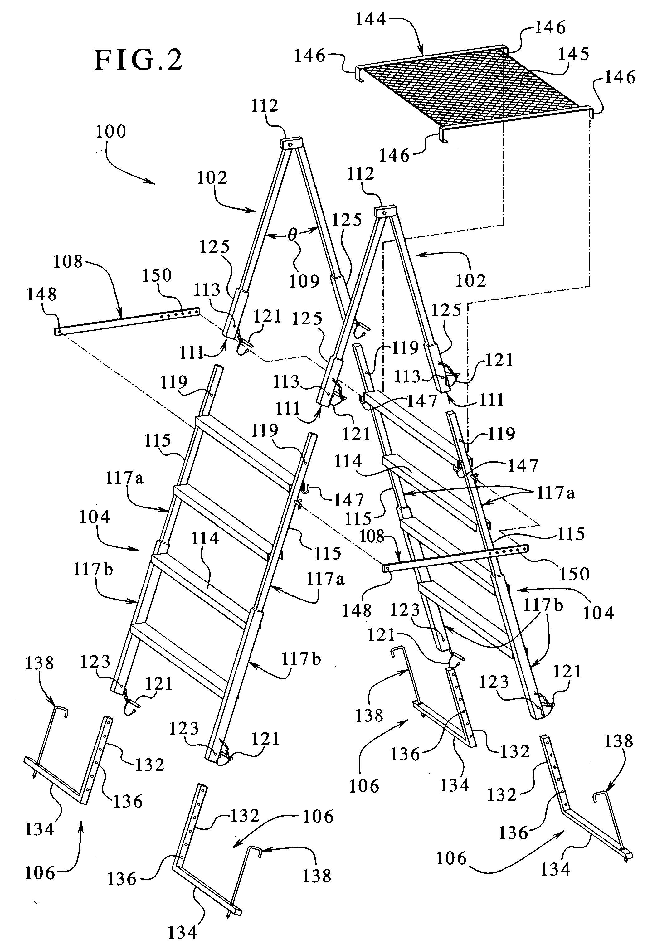
[0041] Referring to FIGS. 1 to 7B, in one embodiment, the portable barrier crossover device or crossover device 100 includes a pair of top assemblies or support members 102, a pair of bottom assemblies or support members 104 which are each connected to the top support members on each side of the top support member, feet assemblies or base supports or stabilizers 106 which are adjustably connected to each of the bottom support members 104 to adjust the height of each side of the crossover device and cross supports 108 which are adjustable and secure a designated angle Θ labeled as 109 formed between the different sides of the crossover device and provide stability to the crossover device.

[0...


PUM


Abstract

A barrier crossover device which is transportable between different remote locations to enable a user to cross over a barrier such as a fence. The crossover device includes a first support and a second support hingedly connected together and a pair of side members. The side members each include at least one step and are connectable to the first and second supports on each side of the crossover device. The crossover over device also includes a platform which is positionable over at least two of the steps and adapted to support the weight of a user. The crossover device includes a pair of base members each including a stabilizer which are movably connected to each side member to adjust the height of the crossover device. Each stabilizer being movable through the base members to secure the base members in the underlying support surface.

Description

BACKGROUND OF THE INVENTION [0001] Several different types of ladders, step stools and other devices exist to perform different functions. Some ladders such as extension ladders are used to reach high places such as second floor windows or gutters on a house. These ladders are typically portable and thereby transferable from one location to the next. Smaller type ladders such as step ladders are used to reach areas which are just out of a person's reach such as the top shelf of a cabinet, a light on the ceiling or other similar area. Smaller step stools are also used by smaller people such as children to reach sinks, table tops or other areas which are otherwise difficult for the children to get to. Therefore, ladders assist users to perform a number of different functions. [0002] Ladders or step devices also include platforms which are connected to the ladders and hold a container, tools or other devices for a user while the user performs some function such as painting a wall or ce...

Claims


Application Information

Patent Timeline
Patent Type & Authority Applications(United States)
IPC IPC(8): E06C7/16
CPCE06C1/39E06C7/081E06C7/42E06C7/46
Inventor PHILLIPS, ALEXANDER K.STADEL, DONALD L.
Owner PHILLIPS ALEXANDER K
Learn More