
Structure with supporting inflatable beam members, and method for containing and recovering hydrocarbons or toxic fluids leaking from a compromised sub-sea structure

a technology of inflatable beams and beam members, which is applied in the field of inflatable containment structures, can solve the problems of serious compromise of the containment capacity of the structure, and achieve the effect of reducing the risk of leaking hydrocarbons or toxic fluids

Inactive Publication Date: 2019-09-03
DYNAMIC SHELTERS
View PDF26 Cites 0 Cited by
  • Summary
  • Abstract
  • Description
  • Claims
  • Application Information

AI Technical Summary

Benefits of technology

The present invention is about a container that can be easily transported and positioned around a leaking vessel on the seabed floor. It is designed to be resilient and can withstand temporary pressure forces without losing its shape and integrity. The container is made up of a fabric sheet and inflatable beams. Anchor members made of cast concrete or a single, integrated circular member are used to keep the container in place and prevent it from moving or floating away.

Problems solved by technology

Disadvantageously, however, as regards the aforementioned undersea structures of rigid materials and construction, due to their rigid and non-deformable nature such are frequently destroyed and / or their containment capacity seriously compromised when they are exposed to transitory but severe undersea pressure waves caused by, typically, undersea earthquakes.
Specifically, none of the aforementioned prior art teach or suggest a structure is particularly suitable for use undersea in collecting and recovering leaking fluids from a compromised undersea vessel or structure and further capable of withstanding transitory but nonetheless large pressure forces which may occur in areas of the ocean where, for example, there are large undersea currents and / or large pressure waves generated for example by undersea earthquakes.
Nor do any of such prior art structures suggest the affixing of a riser to a central hub mounted on the crown or apex of the resiliently flexible structure, to allow withdrawing of fluid collected from within such enclosure to be pumped to surface and thus recovered.
Nor for that matter does the prior art suggest or teach a method of being able to deploy a structure subsea which is capable of collecting and recovering leaking fluids to surface, yet still being able to withstand large transitory pressure waves which may be present.

Method used


Image

  • Structure with supporting inflatable beam members, and method for containing and recovering hydrocarbons or toxic fluids leaking from a compromised sub-sea structure
  • Structure with supporting inflatable beam members, and method for containing and recovering hydrocarbons or toxic fluids leaking from a compromised sub-sea structure
  • Structure with supporting inflatable beam members, and method for containing and recovering hydrocarbons or toxic fluids leaking from a compromised sub-sea structure

Examples


Embodiment Construction

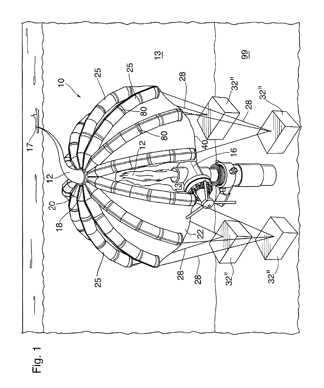
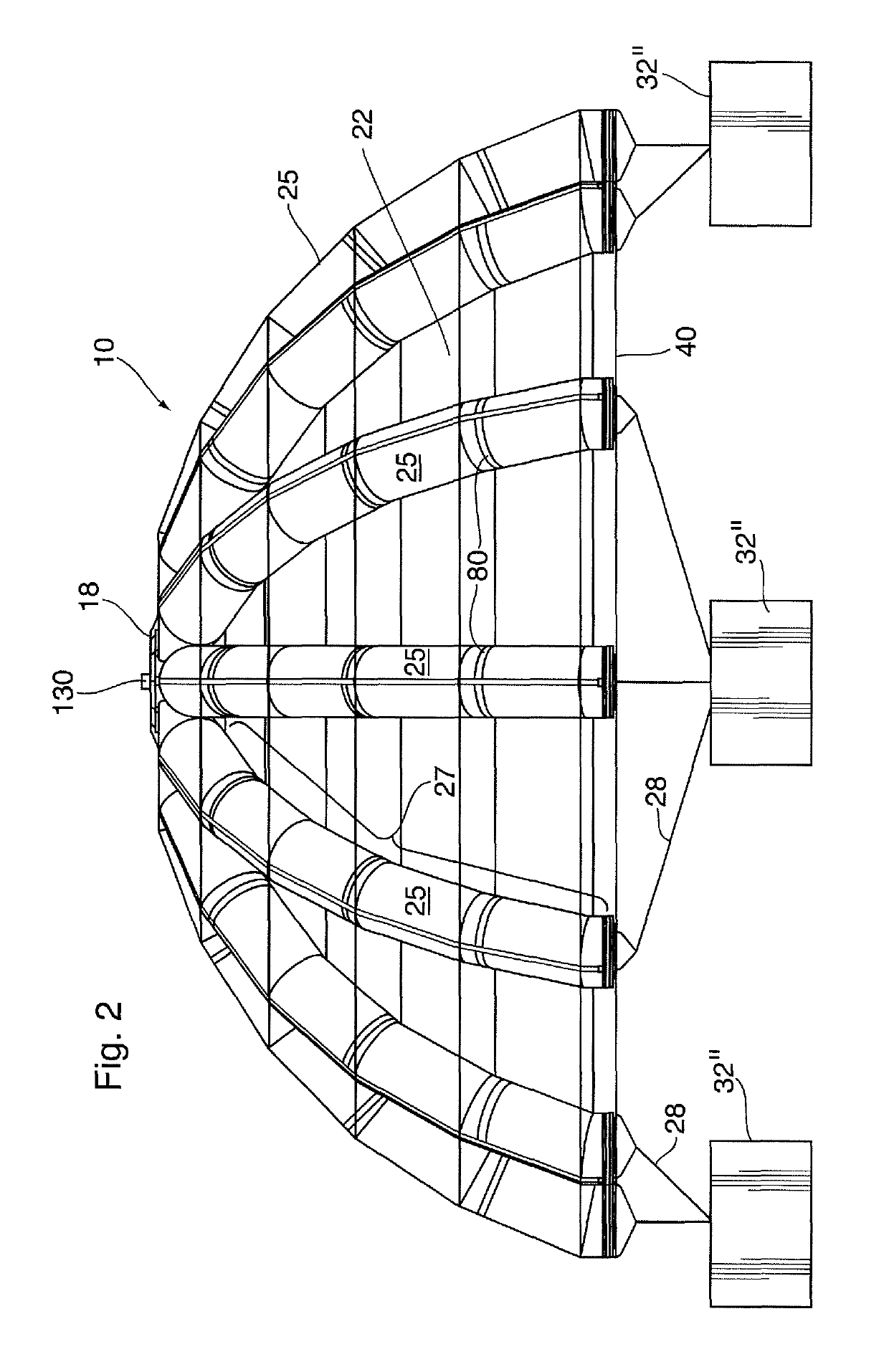
[0082]FIG. 1 shows one embodiment of the containment structure 10 of the present invention and its method of use in an embodiment where such structure 10 is used for collecting a first fluid 12 (in the embodiment shown, leaking hydrocarbon fluids and gases) escaping from a compromised oil well 16, which results in the separation of collected fluid 12 from surrounding seawater 13 and allows pumping of such collected fluid 12 without enrtrained seawater to a vessel 17 at surface.

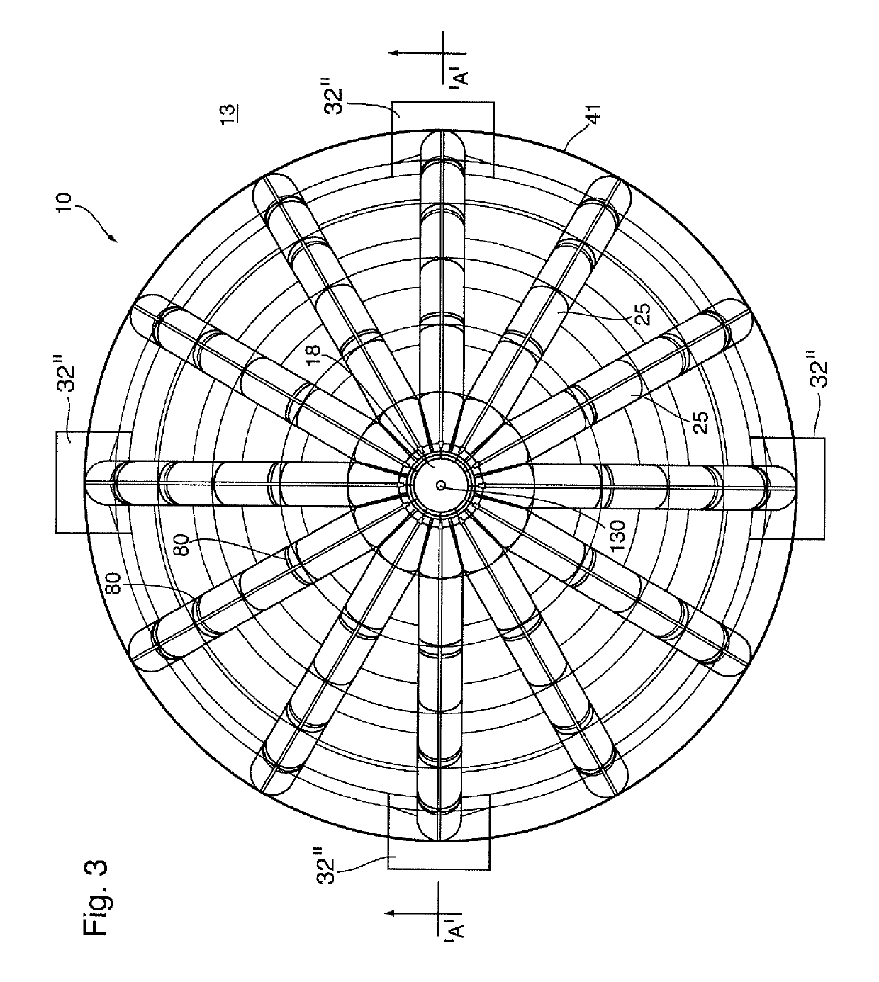
[0083]FIG. 5 shows another embodiment of the containment structure 10 and FIG. 7 shows yet another variation of the hemispherical dome containment structure 10 of the present invention and its method of deployment.

[0084]The containment structure 10 shown in each of FIGS. 1 & 5 is shown in a particular use to which it is particularly suited (but not necessarily only capable of being used in), namely as a sub-sea structure for containing and collecting therewithin a first fluid 12, which may take the form of liq...


PUM


Abstract

A resiliently deformable containment structure having an open bottom end and a raised center portion. A central hub, situated centrally in a textile containment sheet, is provided. A plurality of elongate inflatable beam members are arranged circumferentially around the central hub, each extending radially outwardly and in a downwardly-extending manner therefrom and each underlying or overlying the textile containment sheet to support, when inflated, the textile containment sheet in a downwardly-extending shape to form an enclosure having an open bottom end. Distal ends of the inflatable beam members are tethered to one or more anchor members situated below the open bottom end of the dome structure. The structure is suited for placement above and over a compromised sub-sea structure for collecting and recovering to surface fluids which may be leaking therefrom. A method for containing and recovering such fluids from a compromised sub-sea structure is further disclosed.

Description

FIELD OF THE INVENTION[0001]The present invention relates to inflatable structures, and more particularly to an inflatable containment structure, and a method using such inflatable containment structure for recovering hydrocarbons or toxic fluids, or mixtures of both, from a compromised sub-sea structure.BACKGROUND OF THE INVENTION[0002]Above-ground inflatable structures / enclosures for sheltering humans and or the contents of such structure and which utilize inflatable supporting beams supporting a flexible skin or sheeting, are generally known.[0003]Commonly-assigned U.S. Pat. No. 9,267,765 teaches one such structure / enclosure which has inflatable supporting beams, which are inflated with air. The structure / enclosure, due to the resilient flexibility of the inflatable beams, produces a structure / enclosure that is specially adapted for an environment such as a war zone, where the structure / enclosure need be resiliently flexible and not totally rigid to thereby better withstand blast...

Claims


Application Information

Patent Timeline
Patent Type & Authority Patents(United States)
IPC IPC(8): E02B15/08E02B15/06E21B17/01E04H15/20E21B43/01E02B15/00
CPCE02B15/0814E02B15/0864E21B17/01E04H15/20E02B15/06E21B43/0122E02B2015/005E02D2600/30E04H2015/201
Inventor WARNER, HAROLDKNAPE, AARON
Owner DYNAMIC SHELTERS
Learn More