
Wind Turbine Tower Section, Wind Turbine Tower and Assembly Method

a technology of wind turbines and parts, applied in the direction of machines/engines, mechanical equipment, final product manufacturing, etc., can solve the problem that the parts cannot be transported together, and achieve the effect of easy and fast transportation and assembly, increased life, and reduced cos

Active Publication Date: 2018-03-29
ARCELORMITTAL INVESTIGACION Y DESARROLLO SL
View PDF0 Cites 2 Cited by
  • Summary
  • Abstract
  • Description
  • Claims
  • Application Information

AI Technical Summary

Benefits of technology

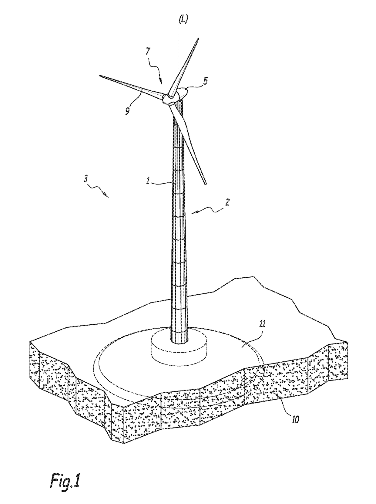
This patent aims to create a wind turbine tower that is strong, durable, and easy to transport and assemble at a lower cost.

Problems solved by technology

Due to their large dimensions, such towers cannot be transported assembled.

Method used


Image

  • Wind Turbine Tower Section, Wind Turbine Tower and Assembly Method
  • Wind Turbine Tower Section, Wind Turbine Tower and Assembly Method
  • Wind Turbine Tower Section, Wind Turbine Tower and Assembly Method

Examples


first embodiment

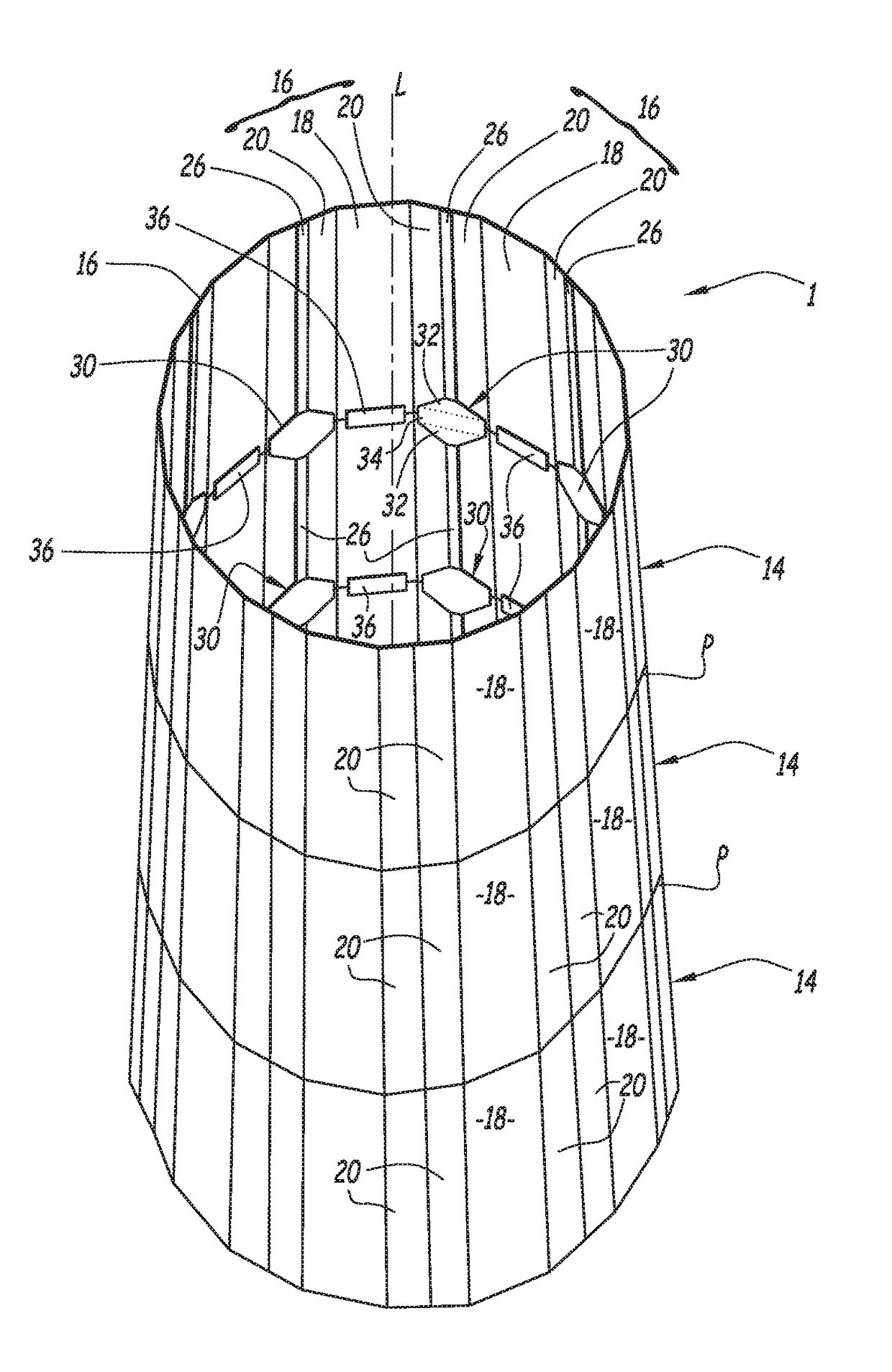
[0097]In reference to FIGS. 7 to 9, we will now more particularly describe a tower section 1 according to a This tower section 1 has all of the features previously described. It also has the more specific features described below.

[0098]In this first embodiment, all of the tower elements 14 of the tower section 1 have the same angular orientation. The longitudinal edges of a wall segment 16 of the upper tower element 14 are situated in the extension of the longitudinal edges of the adjacent wall segment 16 of the lower tower element 14. Each first connector 26 of the upper tower element 14 is arranged in the extension along the longitudinal direction of a first connector 26 of the lower tower element 14.

[0099]Each second connector 30 is inserted, in the longitudinal direction, between a first connector 26 of the upper tower element 14 and a first connector 26 of the lower tower element 14. Each second connector 30 is positioned edge to edge with the first connectors 26 that frame it...

second embodiment

[0110]FIGS. 10 to 11 more particularly illustrate a tower section 1 according to a

[0111]This tower section 1 has all of the features previously described in light of FIGS. 1 to 6. It also has the more specific features described below.

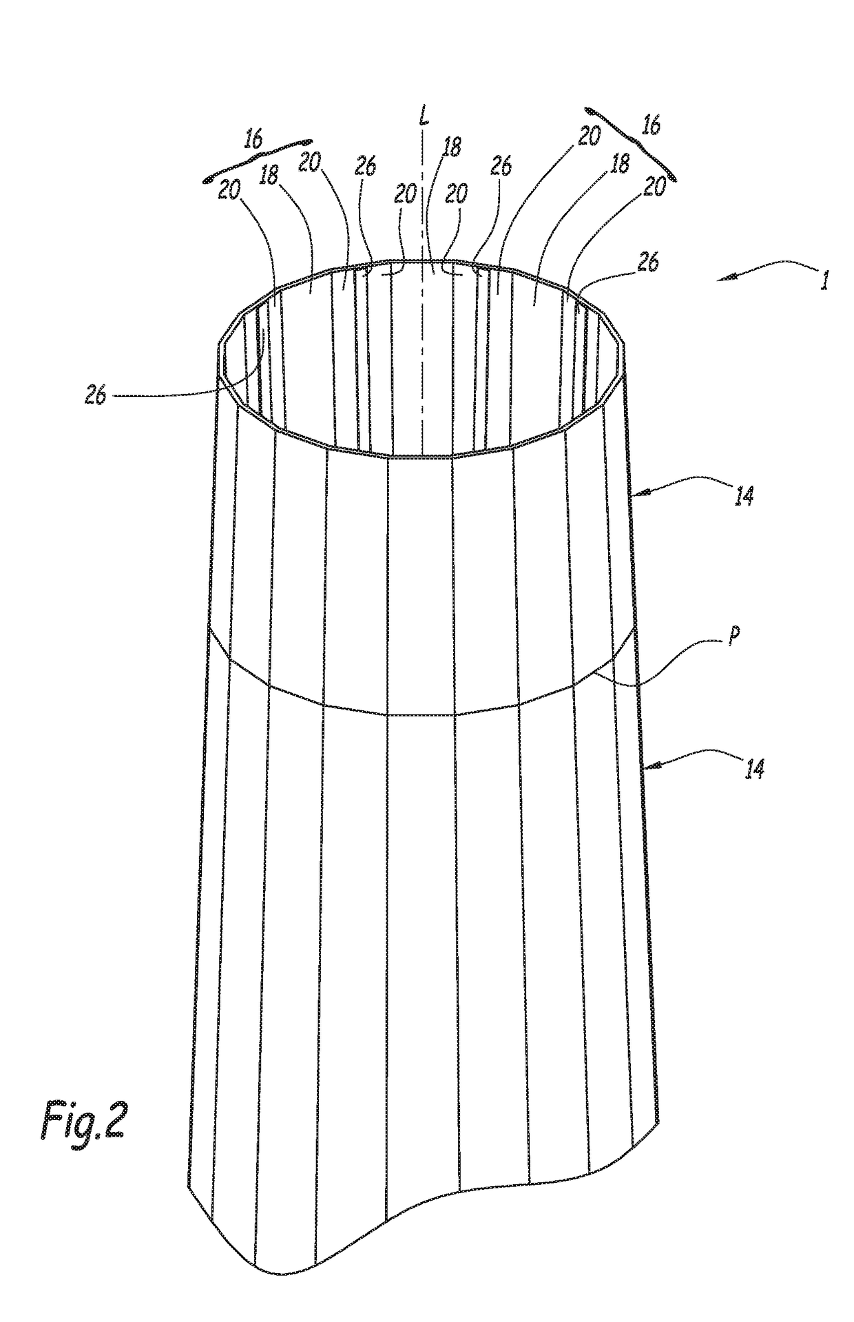
[0112]In the second embodiment, the longitudinally adjacent tower elements 14 are angularly offset relative to one another such that the longitudinal edges of a wall segment 16 of the upper tower element 14 are not in the extension of the longitudinal edges of the longitudinally adjacent wall segment 16 of the lower tower element 14. In other words, the joining lines between circumferentially adjacent wall segments 16 of the upper tower element 14 are angularly offset relative to the joining lines between circumferentially adjacent wall segments 16 of the lower tower element 14. They do not extend in the extension of one another in the longitudinal direction.

[0113]In the case of wall segments 16 comprising a central panel 18 and two side panels 20, eac...


PUM


Abstract

The present invention provides a tower section for a wind turbine which includes at least two tower elements stacked and arranged edge-to-edge at a joining plane, each tower element includes at least two wall segments, connected to one another by first connectors. The tower section further includes second connectors each extending astride the two adjacent tower elements along the longitudinal direction. Each second connector extends in the longitudinal extension of a first connector and has a width increasing, from the first connector, from a first width substantially equal to the width of the first connector to a second width strictly larger than the first width, the second width being reached before the joining plane starting from the first connector.

Description

[0001]The present invention relates to a tower section for a wind turbine having a longitudinal central axis extending along a longitudinal direction, the tower section comprising at least two tubular tower elements stacked along the longitudinal direction and arranged edge-to-edge on a joining plane, each tower element comprising at least two wall segments, connected to one another by first connectors extending along longitudinal edges of the wall segments, the tower section further comprising second connectors each extending astride the two adjacent tower elements along the longitudinal direction.BACKGROUND[0002]Efforts to improve the energy efficiency of wind turbines have led, over time, to an increased size of the turbines, requiring towers with an increased height and diameter to support them. Due to their large dimensions, such towers cannot be transported assembled. Consequently, the towers are generally transported in portions to their installation site, before being assemb...

Claims


Application Information

Patent Timeline
IPC IPC(8): E04H12/34E04H12/08F03D13/20
CPCE04H12/342E04H12/08F03D13/20F05B2230/60F05B2240/912E04H12/085Y02E10/728F03D13/10Y02P70/50Y02E10/72
Inventor GREMLING, MICHAEL
Owner ARCELORMITTAL INVESTIGACION Y DESARROLLO SL
Learn More