Leak resistant drinking cup

a technology for drinking cups and drinking cups, applied in drinking cups, valve types, transportation and packaging, etc., can solve the problems of difficult child use, leakage of drinking water, and seals that require a lower vacuum pressure to open may not be tightly sealed, etc. children will have to suck with significant effort to get the valv

a technology for drinking cups and drinking cups, applied in drinking cups, valve types, transportation and packaging, etc., can solve the problems of difficult child use, leakage of drinking water, and seals that require a lower vacuum pressure to open may not be tightly sealed, etc. children will have to suck with significant effort to get the valv

US20060169694A1Inactive Publication Date: 2006-08-03HANDI CRAFT

Image

  • Leak resistant drinking cup
  • Leak resistant drinking cup
  • Leak resistant drinking cup

Examples


Embodiment Construction

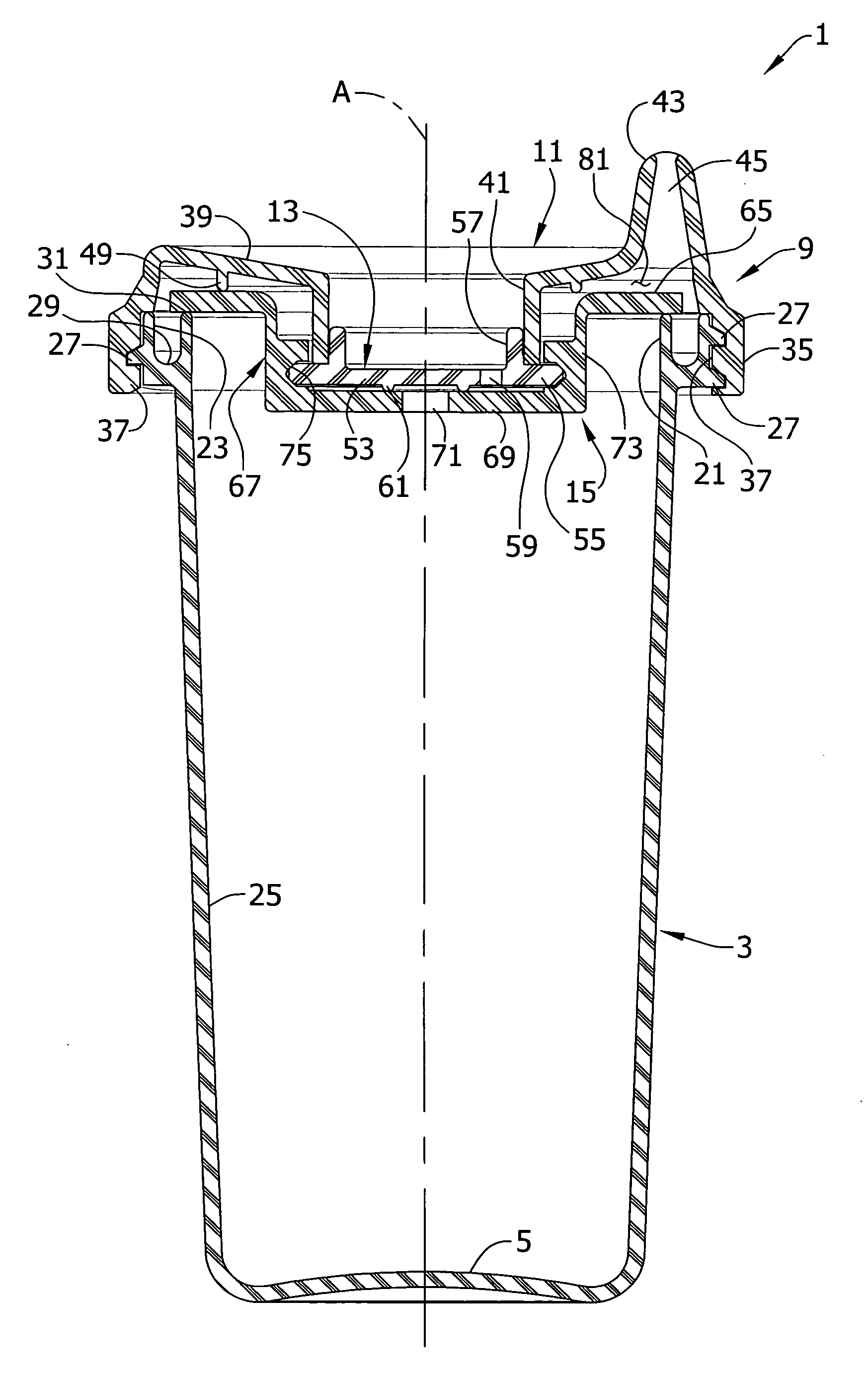
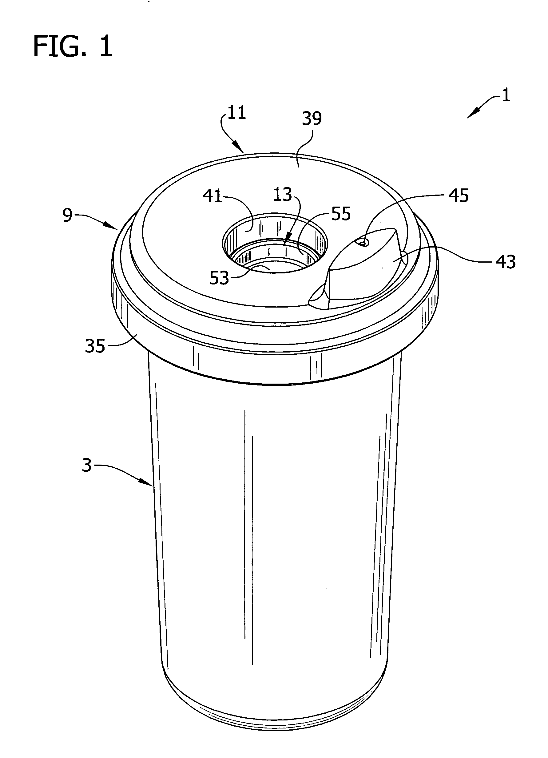
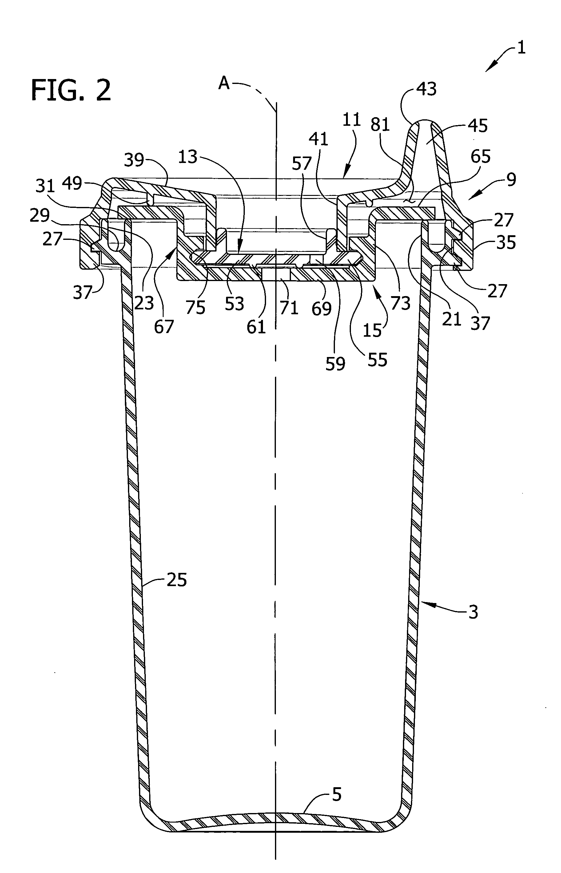
[0026] Referring now to the drawings and in particular to FIGS. 1, 2 and 4, a drinking cup of a first embodiment (generally indicated at 1) constructed according to the principles of the present invention is shown to comprise a container (generally indicated at 3) having a closed bottom 5 and an open top 7 for holding a quantity of liquid to be consumed by a user, such as a small child (not shown). A lid assembly 9 comprises a cover 11 and a retainer 13 made of a suitable material such as polypropylene (the reference numbers indicate their subjects generally). A flexible diaphragm seal indicated generally at 15 is disposed between the cover 11 and an interior space of the container 3. The diaphragm seal 15 can be made of silicone or other appropriate material. The cover 11, retainer 13 and diaphragm seal 15 can be made any desired color or colors, and may be transparent or translucent. As described more fully hereinafter, the diaphragm seal 15 is operable to block the flow of liquid...


PUM


Abstract

A leak resistant drinking cup has a diaphragm seal for normally closing an open top of a liquid container of the cup. The seal can be opened to permit liquid to flow past it and out of the cup upon application of a vacuum pressure by the person, typically a small child, drinking from the cup. The diaphragm seal has a peripheral edge margin that can be deflected upward by the vacuum pressure to open a path out of the drinking cup. A hold down rib may be employed to control the locations where the peripheral edge margin is permitted to deflect.

Description

BACKGROUND OF THE INVENTION [0001] This invention relates generally to leak resistant vessels and more particularly to vessels which permit, in a controlled manner, passage of liquid out of the vessel upon demand. [0002] Vessels of the type to which the present invention relates are most commonly in the form of drinking cups used for small children. The cups are configured so that if they are turned over, liquid inside the cup is prevented from spilling out of the cup by a valve arrangement that seals the cup when not used. Usually the cup has a relatively rigid cover formed with a spout that the child puts his lips on to drink from the cup. The cover can be releasably attached (e.g., snapped or screwed on) to a container portion of the cup over an open top of the container portion, to close the open top. The valve is arranged between the cover and the container portion can be opened to allow liquid to pass out of the cup for drinking. Most commonly, the valve is actuated by a vacuu...

Claims


Application Information

Patent Timeline
03 Aug 2006
Publication
US20060169694A1
IPC
B65D51/16; A47G19/22
CPC
A47G19/2272; F16K15/144; F16K15/148; B65D51/16; A47G19/22
Inventors
KEMPER, BERNARD J.