Ceiling fan

a ceiling fan and fan body technology, applied in the field of ceiling fans, can solve the problems of reducing air movement throughout the room, reducing the basic layout of a generally circular fan body with a plurality of horizontally extending blades, and unable to achieve adequate air movement within the room without generating higher than desired airflow speed

Inactive Publication Date: 2006-08-03
JOHNSON AARON
View PDF2 Cites 44 Cited by
  • Summary
  • Abstract
  • Description
  • Claims
  • Application Information

AI Technical Summary

Problems solved by technology

However, the basic layout of a generally circular fan body with a plurality of horizontally extending blades has not changed.
This further diminishes air movement

Method used


Image

  • Ceiling fan
  • Ceiling fan
  • Ceiling fan

Examples


Embodiment Construction

[0016] It will be understood by those skilled in the art that variations on the details described herein are contemplated within the scope of the invention. In particular, any known alternative technique for hanging the fan may be used in place of the one described herein. In addition, the precise curvature and orientation of the blades may be varied as described herein.

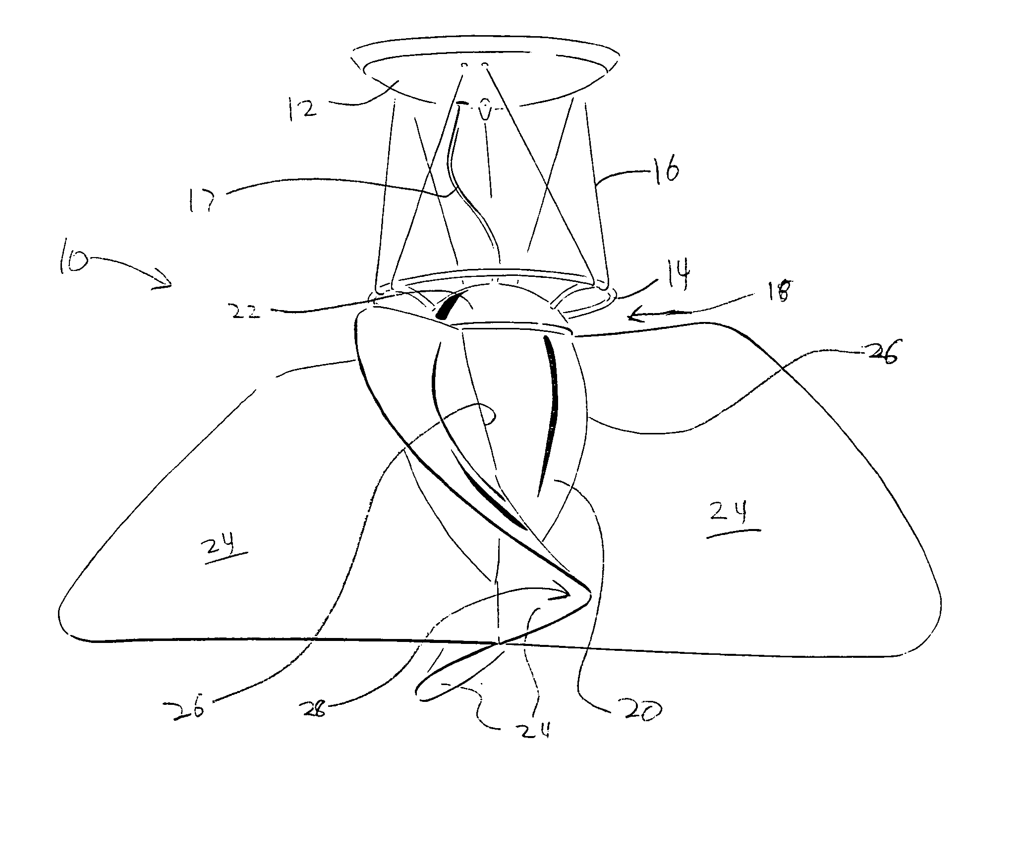
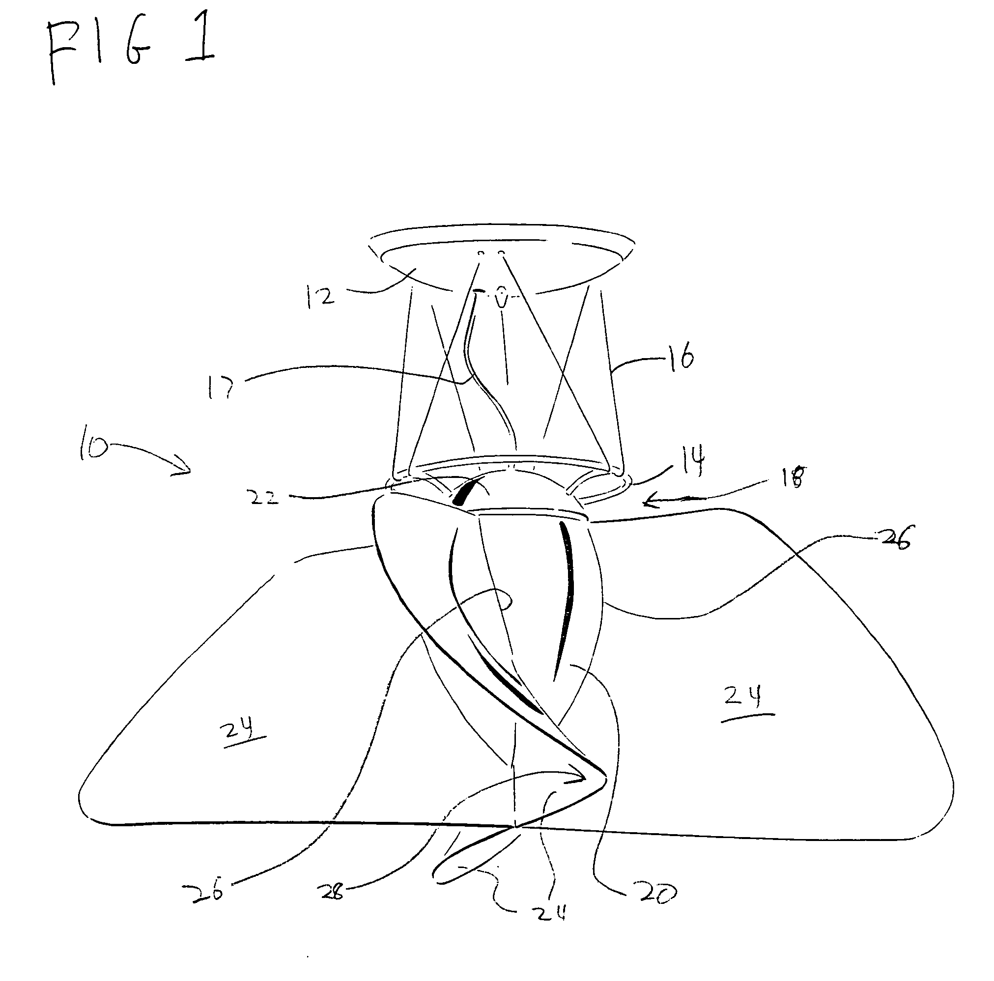
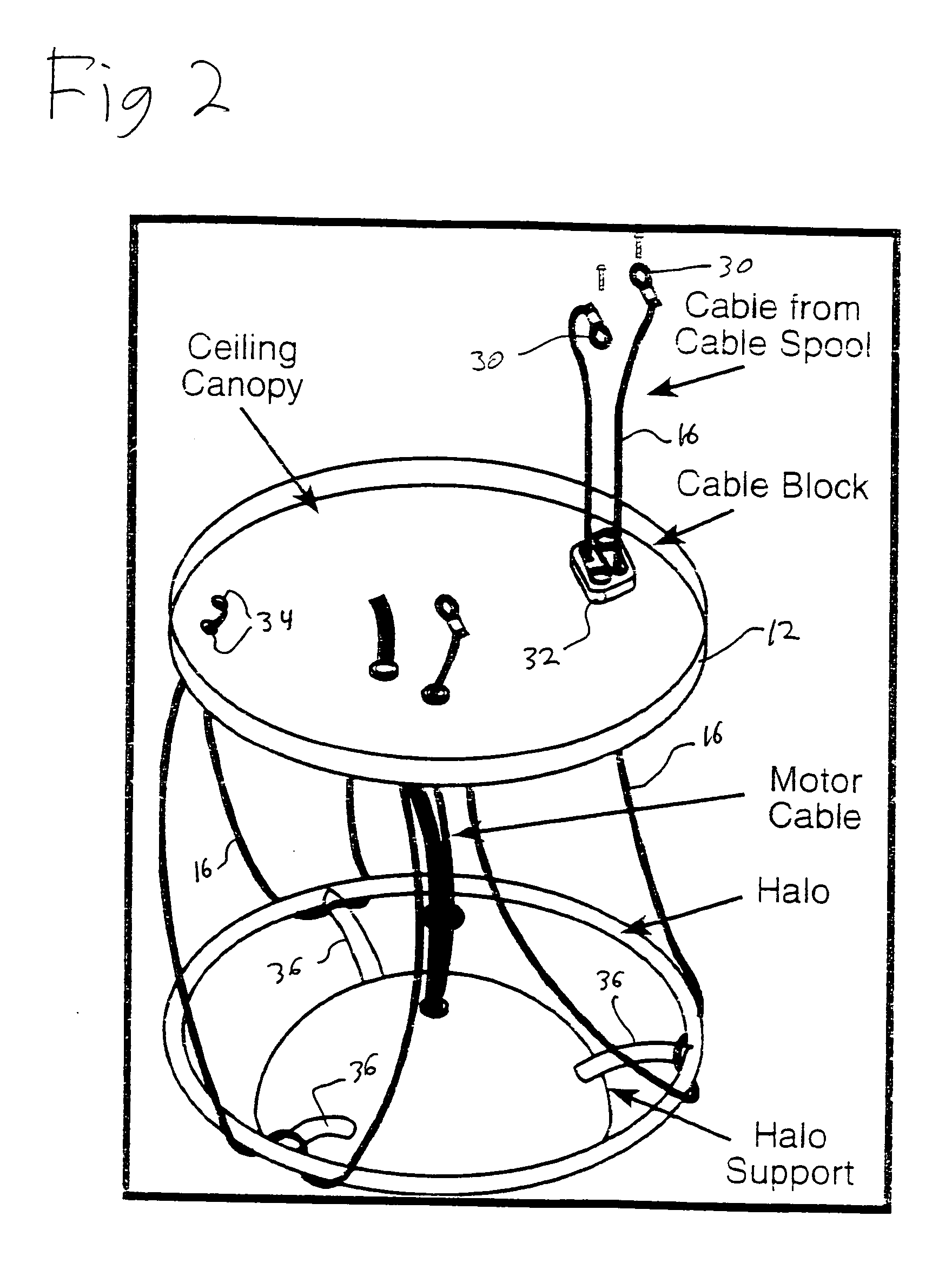
[0017]FIG. 1 illustrates a ceiling fan 10 in accordance with the present invention. A canopy 12 is attached to the ceiling or other mounting point for the fan, and covers typical mounting and electrical connection hardware (not shown) as is known in the art. The fan itself is suspended from a support ring 14, which is connected to the canopy 12 by a flexible cable 16. A power cable 17 extends through canopy 12 to provide power to the fan motor. Further details of this mounting technique are described in connection with FIG. 2. In addition, the mounting technique is similar, but not identical, to the description cont...


PUM


Abstract

A ceiling fan design incorporates a plurality of air-moving blades having a generally vertical orientation. Curvature of the blades causes air to be moved in a generally downward direction. Large blade surface areas are provided to generate desired volumes of air movement at slow speeds.

Description

BACKGROUND OF THE INVENTION [0001] 1. Field of the Invention [0002] The present invention relates generally to electric appliances, and more specifically to a ceiling fan suitable for use in residential or commercial installations. [0003] 2. Description of the Prior Art [0004] Ceiling fan designs are similar to those developed in the early 1900s. A typical ceiling fan has an electric motor suspended from a rigid downrod, allowing it to be spaced from the ceiling. A plurality of fan blades, in typically three to six blades, extend horizontally from the fan motor housing and are attached to a rotor. [0005] In order to obtain different design looks, and achieve differentiation in the marketplace, numerous variations on the basic design have been developed. Details of the fan body layout, and fan body and blade designs, have been changed. However, the basic layout of a generally circular fan body with a plurality of horizontally extending blades has not changed. [0006] Variations have b...

Claims


Application Information

Patent Timeline
IPC IPC(8): F24F7/00
CPCF04D25/088F04D29/34F04D29/384
Inventor JOHNSON, AARON
Owner JOHNSON AARON
Why Eureka
Try Eureka