Driving crown for chain conveyors

a technology of driving crown and conveyor, which is applied in the direction of conveyors, gearing elements, portable lifting, etc., can solve the problems of difficult cleaning process, increased chain cost, and increased cost of chain

Inactive Publication Date: 2006-08-03
AFHER EUROBELT
View PDF10 Cites 18 Cited by
  • Summary
  • Abstract
  • Description
  • Claims
  • Application Information

AI Technical Summary

Problems solved by technology

The problems arising with this solution are twofold, on the one hand the chain becomes much more expensive, because of the amount of material that is needed to obtain the aforementioned lengthways rib and, on the other hand, its special “anatomy” makes it extremely easy for dirt to build up on it, thereby making the cleaning process more difficult.
This problem gets worse when the chain conveyor is given over to driving products that generate greasy deposits, which pass through the links of the chain itself, these then being deposited on the outside of the driving crowns, and because of the way that these deposits gradually dry up, as well as because of the build up of dust, they form a pasty and very thick mass, which has a negative effect on the way that the transmission process works.
The basic problem with this solution is that there is only a very small surface area of contact between the cogs on the crown and the links on the chain, so the transferring of stress takes place in a way that is far from ideal, and there is a high risk of the chain slipping with respect to the position of the crowns.

Method used


Image

  • Driving crown for chain conveyors
  • Driving crown for chain conveyors
  • Driving crown for chain conveyors

Examples


Embodiment Construction

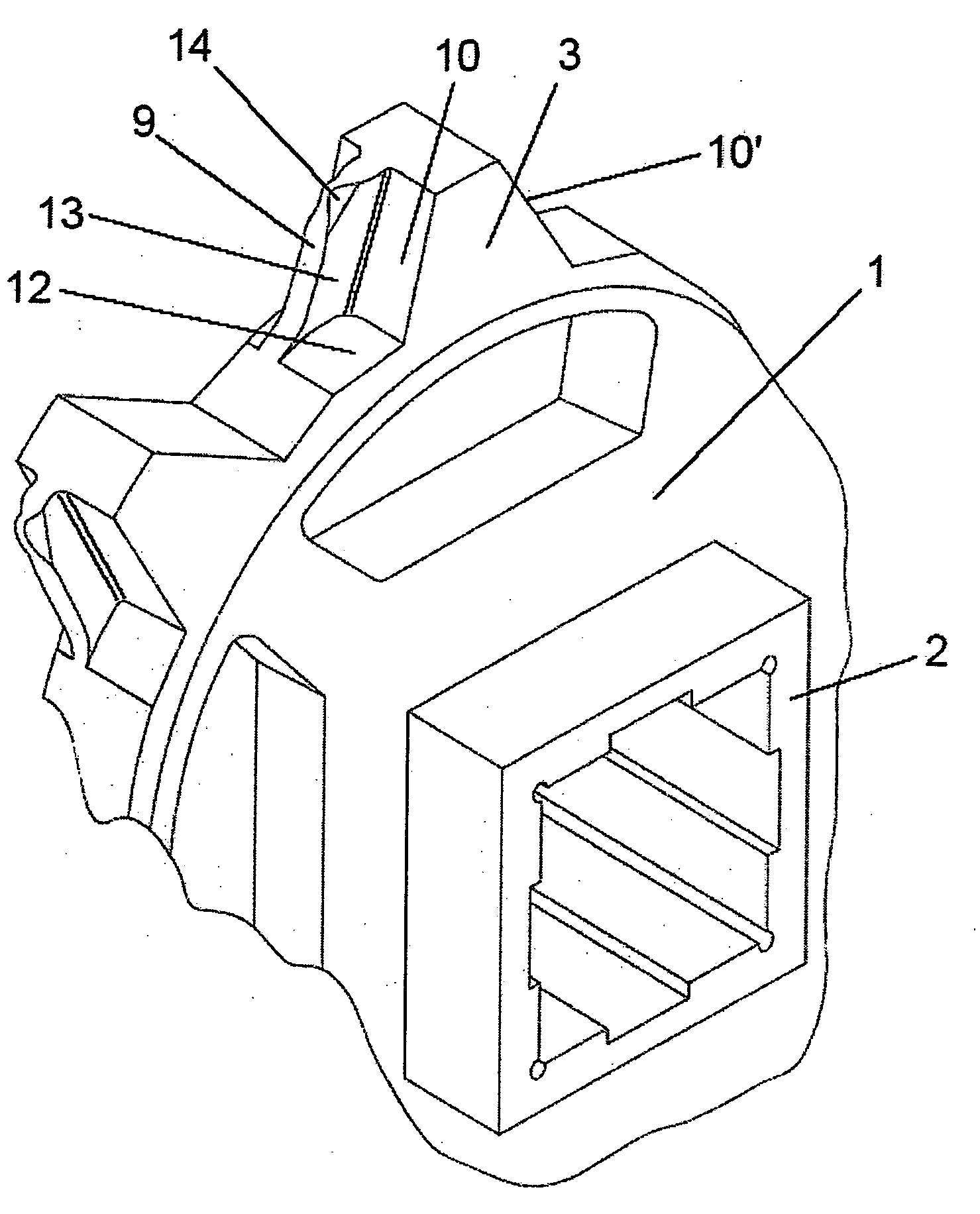
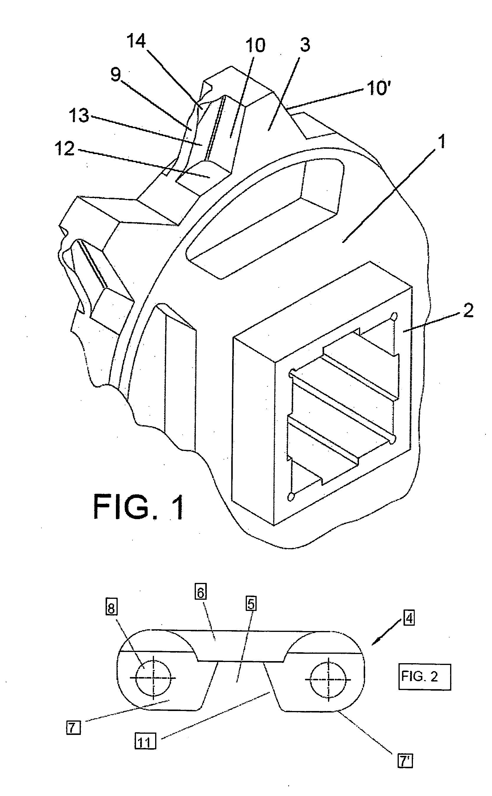
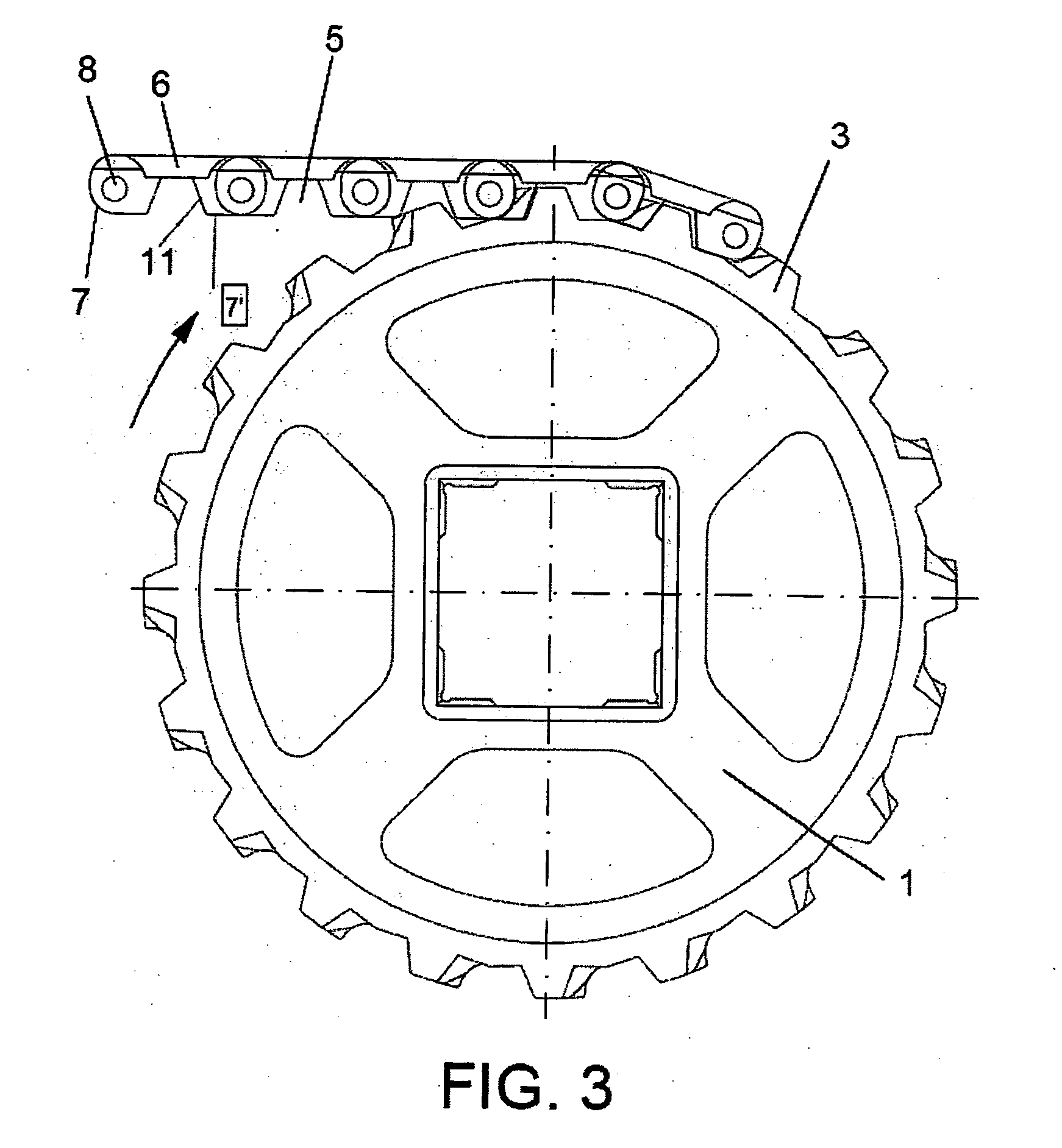
[0010] The main characteristics of the driving crown that is the subject of the invention, which can belong to either of the two types referred to above, that is to say those which have alveoli that receive a central rib running lengthways on the inner surface of the links, or the other ones where the core is not equipped with that rib and the cogs on the driving crown act directly upon the protrusions sticking out from the links, are embodied by the fact that each cog in the crown, equipped to act simultaneously on at least two protrusions of each link in the chain, is also equipped with a crest, which is located on the back surface, which is consistent with the driving direction of the crown itself, suitably laid out and designed to stick into the aforementioned protrusions on the chain, serving as a retention device to hold back the chain axially, in view of the fact that it holds back the links transversally or axially.

[0011] This rear position of the guiding crest causes each ...


PUM


Abstract

Designed to immobilise the chain conveyor to ensure that it does not move transversally, and to make it easier to clean it, the main characteristics being that each one of its cogs (3) is equipped, only on its rear wall (10), with a crest (9) that is off-centre with respect to the imaginary plane and runs perpendicular to the centreline of the crown, which has to be inserted between the protrusions on the links that form the chain. The layout of this crest (9) is trapezoidal and isosceles, diverging towards the cog (3), and the lateral surfaces are concave, in such a way that the aforementioned lateral surfaces are joined to the marginal surfaces of the surface (10) of the cog (3), in a markedly rounded way, so there are no sharp edges, which makes it easy to clean the crown when, for example, a jet of water is sprayed onto it.

Description

OBJECT OF THE INVENTION [0001] This invention is a driving crown, of the kind that is used for moving chain conveyors, to be specific the chains of the type that are structured in the form of a series of links, which are attached to each other by joints, and that are driven by a series of cogged crowns. [0002] The function of the above-mentioned crowns is not only to drive the chain conveyor, but also to stop it from moving sideways. [0003] The object of the invention is to equip that driving crown with certain means for providing the chain conveyor with transversal stabilisation, which will make it possible to considerably improve the way in which the whole assembly is cleaned. BACKGROUND TO THE INVENTION [0004] It is extremely common practice to use chain conveyors that are equipped with plastic links, and there are a host of devices of this type. [0005] One of the most common examples of such practice is the one where each link, whether a single piece or modular, contains a flat ...

Claims


Application Information

Patent Timeline
Patent Type & Authority Applications(United States)
IPC IPC(8): F16H7/06F16H55/30B65G23/06
CPCB65G23/06F16H55/30
Inventor SAN MIGUEL NUNEZ, JAVIERSAN MIGUEL NUNEZ, MARTA
Owner AFHER EUROBELT
Why Eureka
Try Eureka