Ventilation interface

a technology of ventilation interface and mask, which is applied in the field of respiration or breathing assist mask, can solve the problems of obstructing sleep apnea syndrome, affecting the sleep quality of patients, and affecting the quality of life of patients,

Inactive Publication Date: 2006-08-10
SALTER LABS LLC
View PDF43 Cites 274 Cited by
  • Summary
  • Abstract
  • Description
  • Claims
  • Application Information

AI Technical Summary

Problems solved by technology

However, in those individuals having a relatively smaller-sized throat passage, the narrowed throat passage prohibits the adequate amount of oxygen from flowing into the lungs.
Additionally, a nasal obstruction, such as a relatively large tongue, and / or certain shapes of the palate and / or the jaw of the individual, further prohibit the adequate amount of oxygen from flowing into the lungs.
As a result, the individual suffering from obstructive sleep apnea syndrome generally experiences fragmented sleep that is not restful.
The fragmented sleep results in one or more of excessive and / or inappropriate daytime drowsiness, headache, weight gain or loss, limited attention span, memory loss, poor judgment, personality changes, lethargy, inability to maintain concentration, and / or depression.
Further, prior to, during and / or subsequent to certain medical procedures and / or medical treatments, an individual can be unable to receive the adequate amount of oxygen.
As a result, the harness is generally uncomfortable to wear, particularly when sleeping.
The applied pressure often results in undesirable irritation and sores caused by movement of the mask and harness during periods of both wakefulness and sleep.
Further, the required seal is generally difficult to maintain when the mask and harness is moved.
The force that the harness applied to the mask against the face also applies an undesirable pressure to the sinus area adjacent to the nose, causing the nasal sinus airways to narrow.
Additionally, if the tubing between the mask and the gas supply unit folds undesirably, this problem will be exacerbated.
The above-discussed combination of increased flow velocity and decreased pressure results in the removal of moisture form the mucosal walls during inspiration and may cause an undesirable drying and a burning sensation within the nares.
As a result, the individual may remove the mask to alleviate these discomforts, consequently discontinuing the beneficial application of the positive pressure.
Such increased air flow velocity and decreased pressure deteriorate the laminar flow between the air input and output portions of the conventional mask.

Method used


Image

  • Ventilation interface
  • Ventilation interface
  • Ventilation interface

Examples


Embodiment Construction

[0033] Aspects of the invention are disclosed in the following description and related drawings directed to specific embodiments of the invention. Alternate embodiments may be devised without departing from the spirit or the scope of the invention. Additionally, well-known elements of exemplary embodiments of the invention will not be described in detail or will be omitted so as not to obscure the relevant details of the invention. Further, to facilitate an understanding of the description discussion of several terms used herein follows.

[0034] The word “exemplary” is used herein to mean “serving as an example, instance, or illustration.” Any embodiment described herein as “exemplary” is not necessarily to be construed as preferred or advantageous over other embodiments. Likewise, the term “embodiments of the invention” does not require that all embodiments of the invention include the discussed feature, advantage or mode of operation.

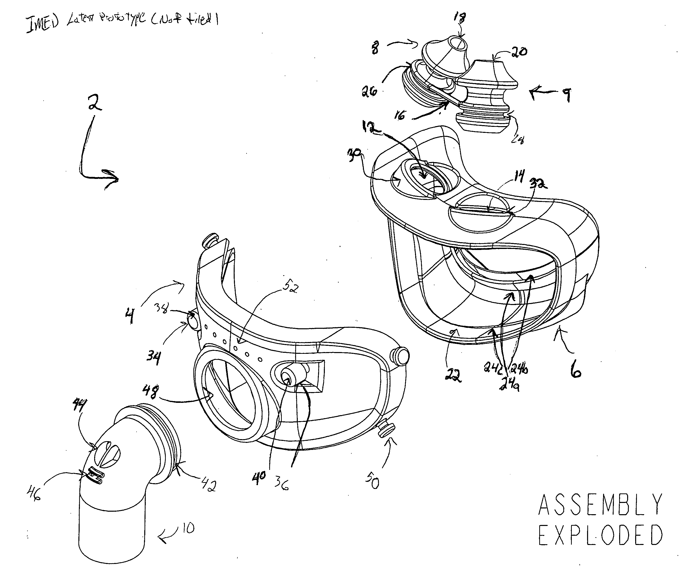
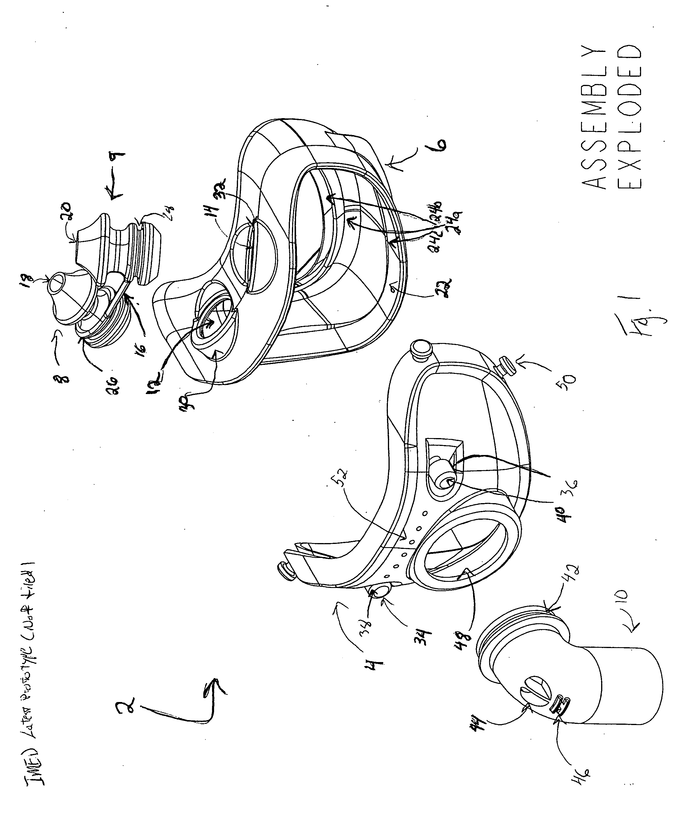
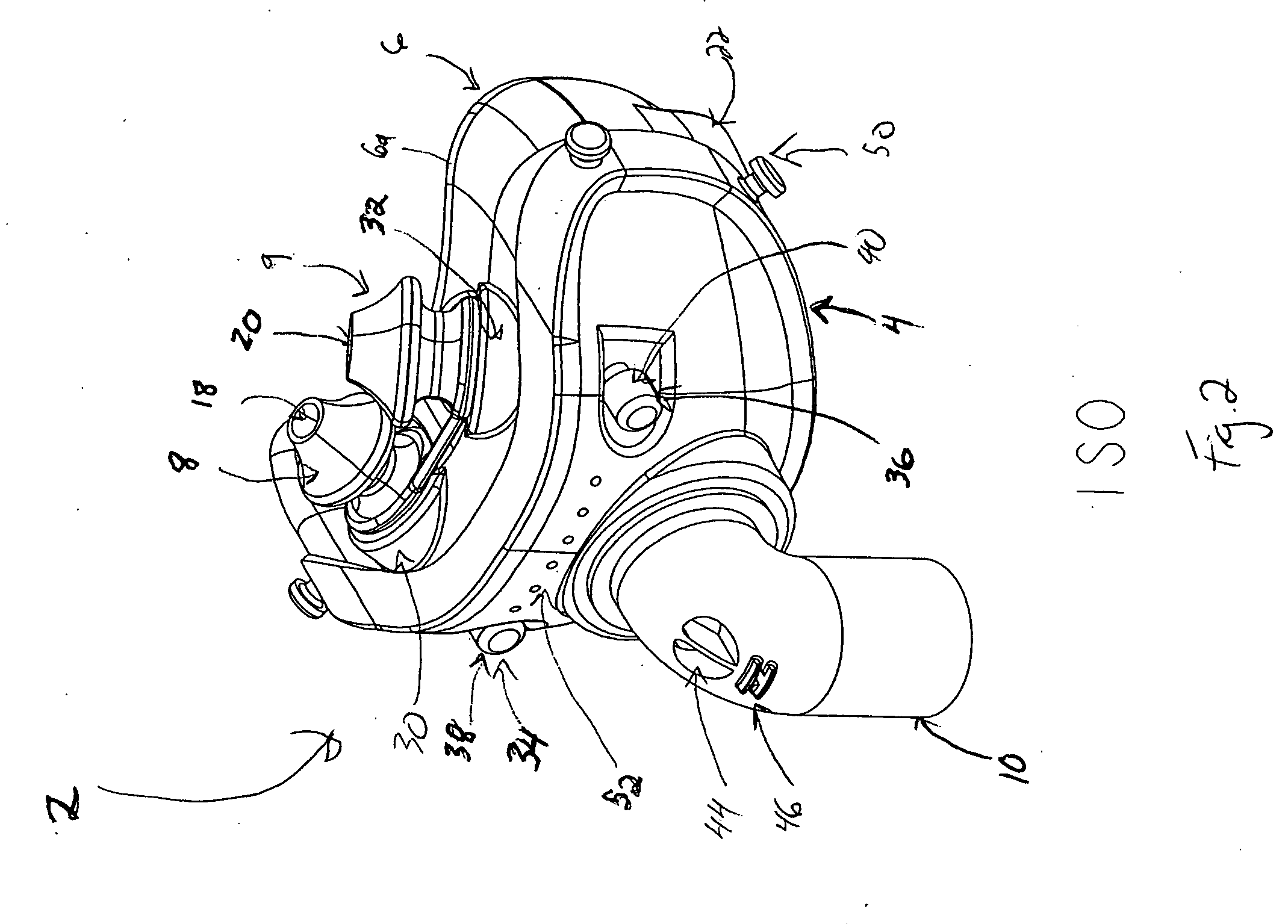
[0035] Generally referring to FIGS. 1-8, a vent...


PUM


Abstract

A respiration assist mask having an input gas feed tube, a ventilation interface, a facial interface and nasal inserts. The gas feed tube can connect to the ventilation interface and form a seal. The ventilation interface may be joined with the facial interface to form a seal between the ventilation interface and the facial interface, as well as between the facial interface and the face of a user. Additionally, nasal inserts may be inserted into a portion of the facial interface and form a seal between the inserts and the facial interface.

Description

PRIORITY CLAIM UNDER 35 U.S.C. §119 [0001] This invention is related to and claims priority under 35 U.S.C. §119 to both U.S. Provisional Patent Application 60 / 634,802, filed Dec. 10, 2004, and U.S. Provisional Patent Application 60 / 645,672, filed Jan. 21, 2005, and the contents of both are hereby incorporated in their entirety.FIELD OF THE INVENTION [0002] This invention relates generally to the field of respiration or breathing assist masks. In particular, the invention relates to respiration or breathing assist masks utilizing both the nose and mouth. BACKGROUND [0003] Obstructive sleep apnea syndrome (commonly referred to as obstructive sleep apnea, sleep apnea syndrome, and / or sleep apnea) is a medical condition that includes repeated, prolonged episodes of cessation of breathing during sleep. During a period of wakefulness, the muscles of the upper part of the throat passage of an individual keep the passage open, thereby permitting an adequate amount of oxygen to flow into th...

Claims


Application Information

Patent Timeline
Patent Type & Authority Applications(United States)
IPC IPC(8): A62B7/10A62B18/08
CPCA61M16/06A62B9/04A61M16/0627A61M16/0666A61M16/0816A61M2210/0625A61M16/0622
Inventor CHANDRAN, SANJAYHERNANDEZ, SHARACOLLAZO, LOUIS JAVIER
Owner SALTER LABS LLC
Why Eureka
Try Eureka