Pressure container in a vibration damper

a pressure container and vibration damper technology, applied in the field of vibration dampers, can solve the problems of affecting the functionality of the vibration damper over the long term, and achieve the effects of simple components, simple geometry, and simple boring operation

Inactive Publication Date: 2006-08-10
ZF FRIEDRICHSHAFEN AG
View PDF22 Cites 0 Cited by
  • Summary
  • Abstract
  • Description
  • Claims
  • Application Information

AI Technical Summary

Benefits of technology

[0007] The great advantage here is that the operating pressure is present at both axial ends of the adapter piece. Depending on the size of the ends subjected to the operating pressure, the forces acting on the adapter piece can be considerably reduced, so that it would be possible to use cheaper grades of material. In addition, the pressure container can also be designed so that there is a certain gap between it and the edges of a piston rod guide, so that no bending loads are imposed on the adapter piece.
[0008] For this purpose, the adapter piece has a cylindrical lateral surface by which it is sealed to the vibration damper. This prevents damping medium from mixing with a gas cushion in the pressure container, which would impair the functionality of the vibration damper over the long term. In addition, the adapter piece needs to be pretensioned only radially in the area of the seal; no axial pretension is required.
[0009] In another advantageous embodiment, the adapter piece has an axial positioning stop, which provides support on the vibration damper side. The positioning stop is a very simple means of ensuring a defined installation position.
[0013] In another embodiment, the adapter piece consists of several parts, where a separate retaining part, which can be connected to the vibration damper, can be connected to the connecting part. The really essential point is that the filling channel on the vibration damper side has a simple geometry and can thus be manufactured by a simple boring operation, for example.
[0014] Thus the retaining part is designed as a tubular body, which is pressed into the connecting part. The tubular body is pressed into the vibration damper first, and the connecting part is then pressed in turn onto the tubular body, which means that very simple components can be used.
[0018] Especially so that a simple filling apparatus can be provided, the closing element is pressed by a pretensioning spring onto the shoulder. By the use of a simple, needle-like tool, the closing element can be moved independently of the pressure inside the pressure container from the closed position on the shoulder to the open position, which releases the filling channel.

Problems solved by technology

This prevents damping medium from mixing with a gas cushion in the pressure container, which would impair the functionality of the vibration damper over the long term.

Method used


Image

  • Pressure container in a vibration damper
  • Pressure container in a vibration damper
  • Pressure container in a vibration damper

Examples


Embodiment Construction

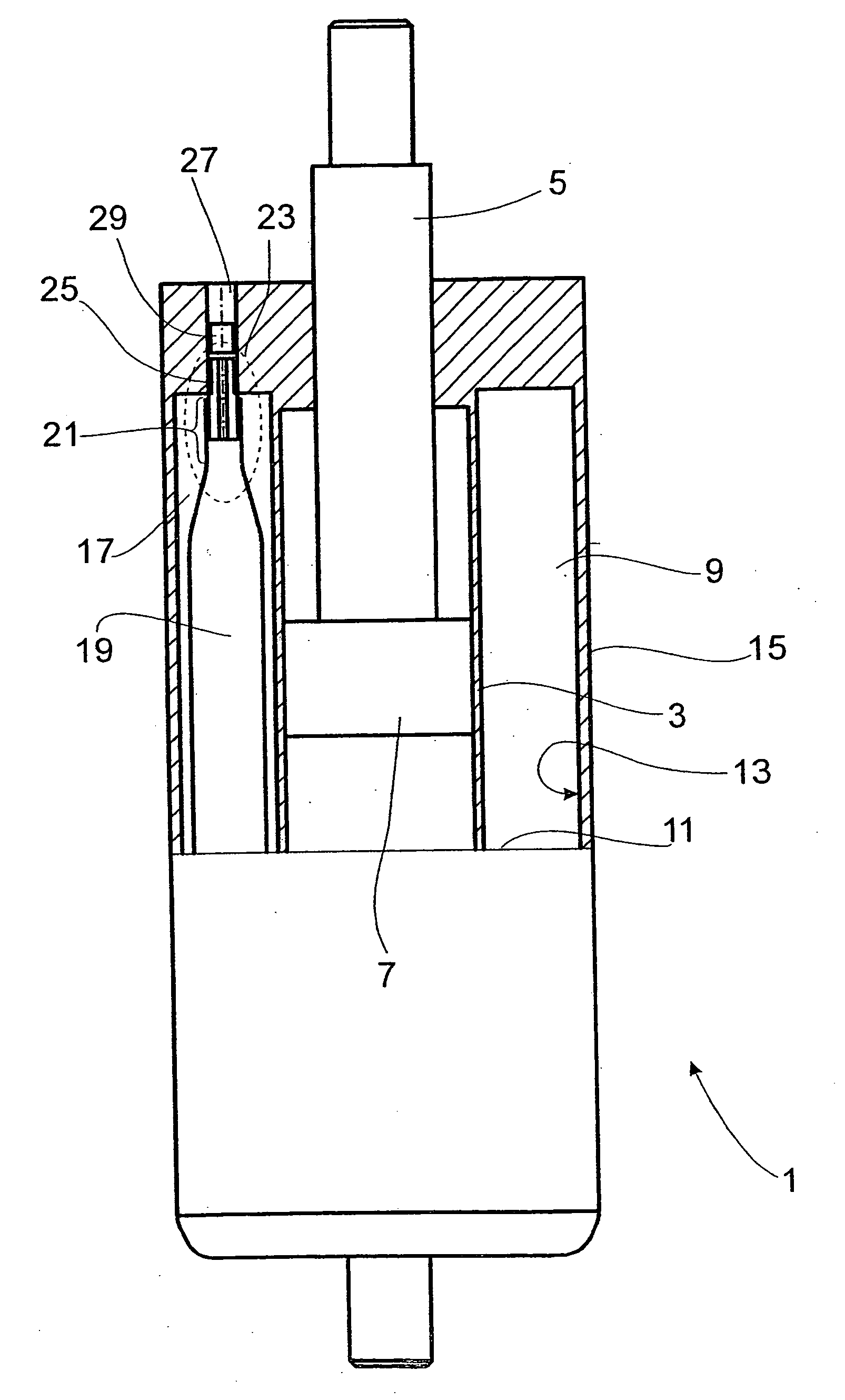
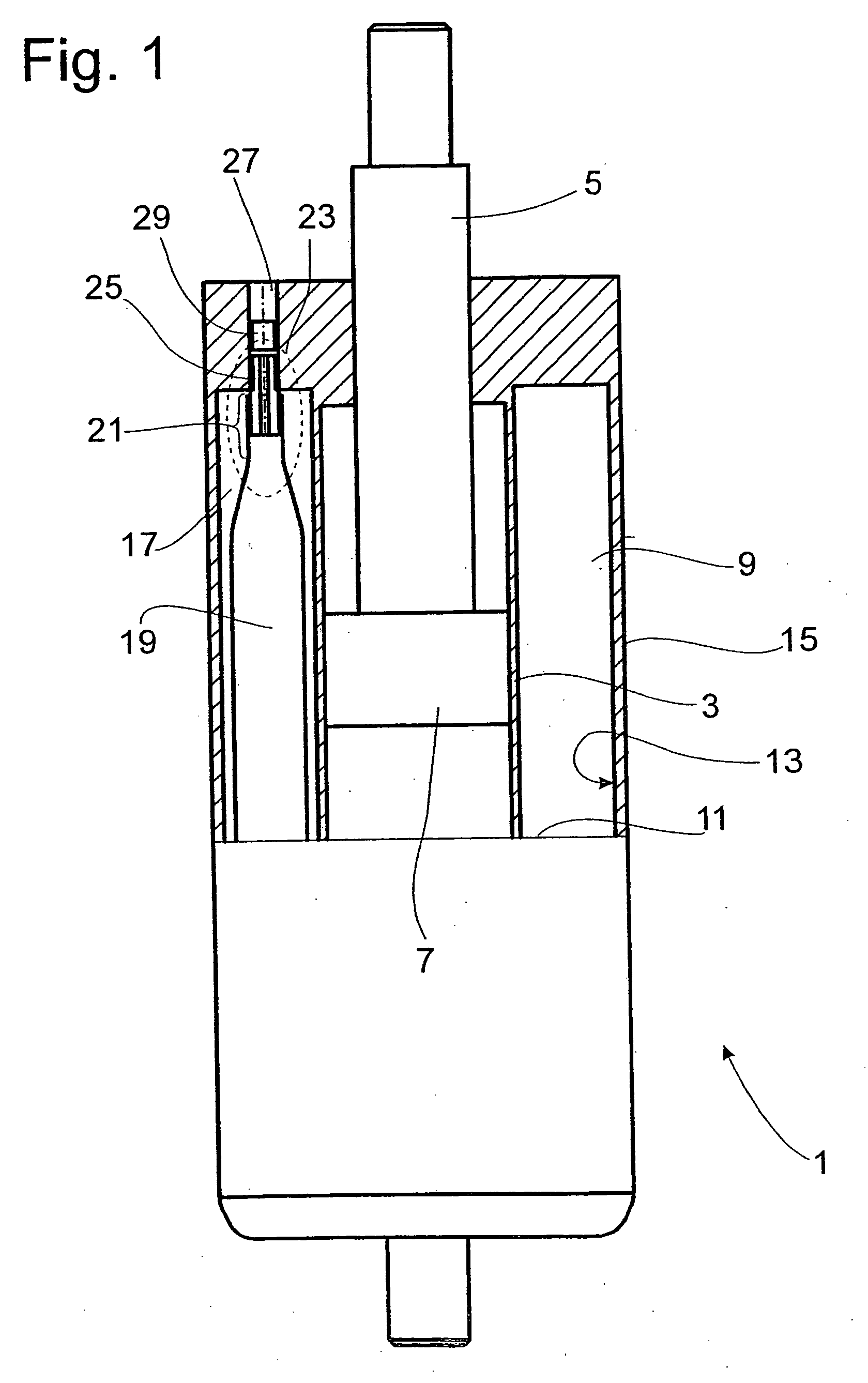
[0030]FIG. 1 shows a simplified diagram of a vibration damper 1 of the two-tube type. The actual design of the damper is not important with respect to the use of the invention.

[0031] The vibration damper 1 has a damping medium-filled cylinder 3, in which a piston rod 5 is free to move axially together with a piston 7. The volume displaced by the inward and outward-traveling piston rod 5 is displaced into a compensating space 9, which is located between the outside wall 11 of the cylinder 3 and an inside wall 13 of a container 15 surrounding the cylinder 3. Inside the compensating space 9, a pressure container 17 is provided, which has a sleeve body 19, into the end 21 of which an adapter piece 23 is fastened, the upper part 25 of which is connected in turn to a filling channel 27 on the vibration damper side. A closing element 29, separate from the adapter piece 23, seals off the filling channel 27. The adapter piece 23 itself has no closing element.

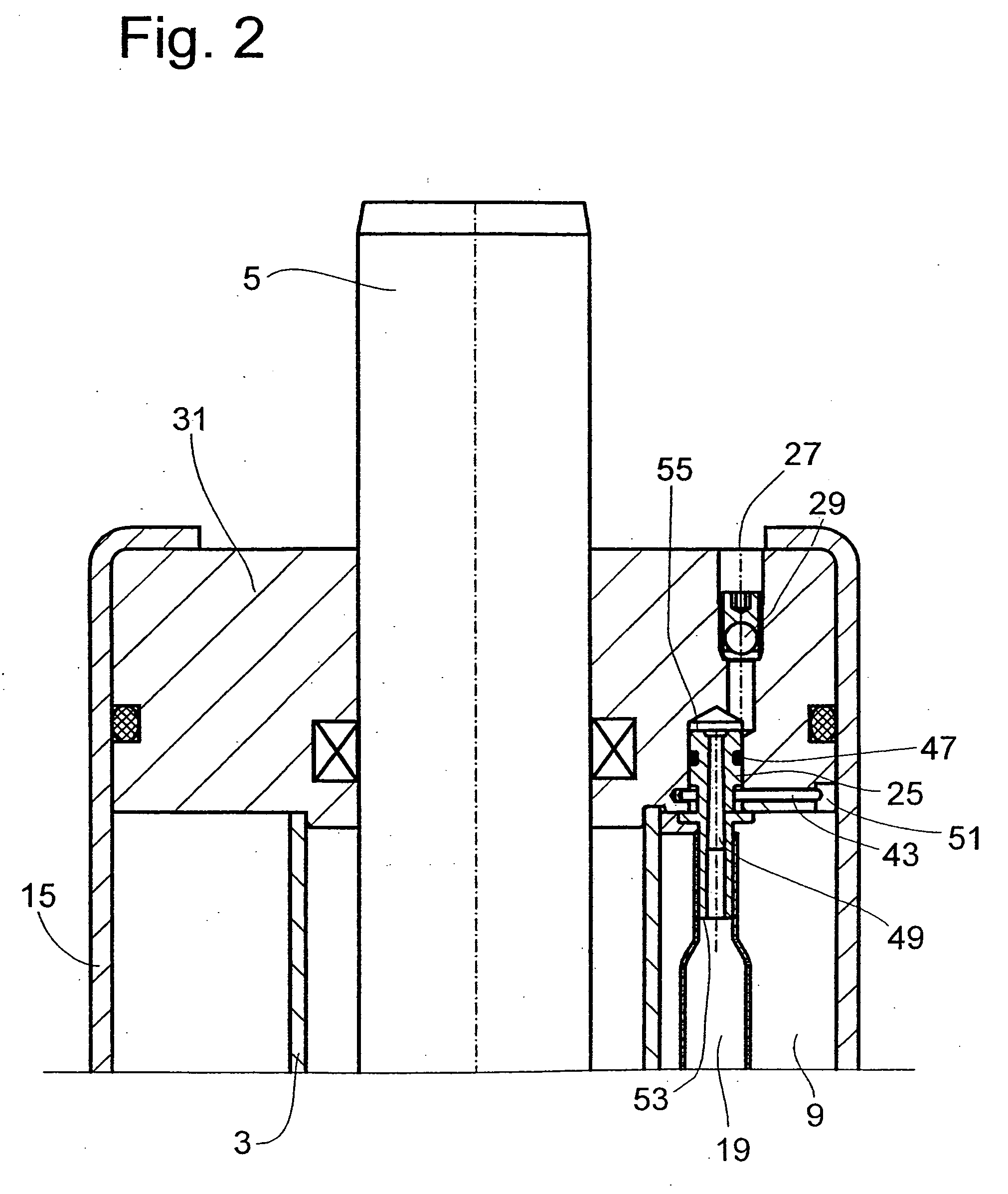
[0032]FIG. 2 shows the upper ar...


PUM


Abstract

Vibration damper with a damping medium-filled cylinder, in which a piston rod is installed with freedom of axial movement, and a pressure container, which is connected to the vibration damper by an adapter piece. The adapter piece comprises a connecting part, which is connected to the pressure container, and an upper part, which is connected permanently to the vibration damper. A filling channel inside the adapter piece is open at both ends when the pressure container is full, and a filling channel on the vibration damper side, which is connected to the filling channel of the adapter piece, has a closing element.

Description

BACKGROUND OF THE INVENTION [0001] 1. Field of the Invention [0002] The invention relates to a vibration damper having a cylinder filled with damping medium, a container surrounding the cylinder and forming a compensating space between the container and the cylinder, an endwall fixed to an end of the container and enclosing an end of the cylinder and an end of the compensating space, a piston rod received through the endwall, and a pressure container in the compensating space. [0003] 2. Description of the Related Art [0004] U.S. Pat. No. 6,467,760 describes a vibration damper with a pressure container inside the compensating space. The pressure container consists of a sleeve welded at the ends, which can be filled with gas through a filling channel, which passes through an adapter piece. For this purpose, one end of the upper part of the adapter is installed completely within the piston rod guide. The adapter piece has a shoulder, which is introduced into a radial groove inside the ...

Claims


Application Information

Patent Timeline
Patent Type & Authority Applications(United States)
IPC IPC(8): F16F9/43
CPCF16F9/092F16F9/43Y10T137/1812Y10T137/7927
Inventor ACKERMANN, NORBERT
Owner ZF FRIEDRICHSHAFEN AG
Why Eureka
Try Eureka