Particle shadow velocimetry

a particle shadow and velocity measurement technology, applied in the direction of liquid/fluent solid measurement, instruments, investigating moving fluids/granular solids, etc., can solve the problems of reducing the detection of particles, and limiting the sampling area to small areas, so as to achieve accurate spatial resolution velocity field and low power

Inactive Publication Date: 2006-08-10
INNOVATIVE SCI SOLUTIONS
View PDF6 Cites 43 Cited by
  • Summary
  • Abstract
  • Description
  • Claims
  • Application Information

AI Technical Summary

Benefits of technology

The present invention is a method for measuring the velocity of particles using light sources. This method can use lower power light sources, such as LEDs, instead of lasers. The method provides accurate information about the velocity of particles in a specific location.

Problems solved by technology

The technical problem addressed in this patent text is the high cost and limited scope of current PIV techniques, which require a powerful laser source and may provide limited data on particle movement. The text describes various PIV techniques and their limitations, including the need for high-speed lasers and high-speed cameras for microscopic PIV and the use of LEDs for studying flows. The text also mentions the use of holography and particle size measurements for velocity measurements. The patent aims to provide a solution to these limitations and provide a more cost-effective and versatile method for studying flows.

Method used


Image

  • Particle shadow velocimetry
  • Particle shadow velocimetry
  • Particle shadow velocimetry

Examples


Embodiment Construction

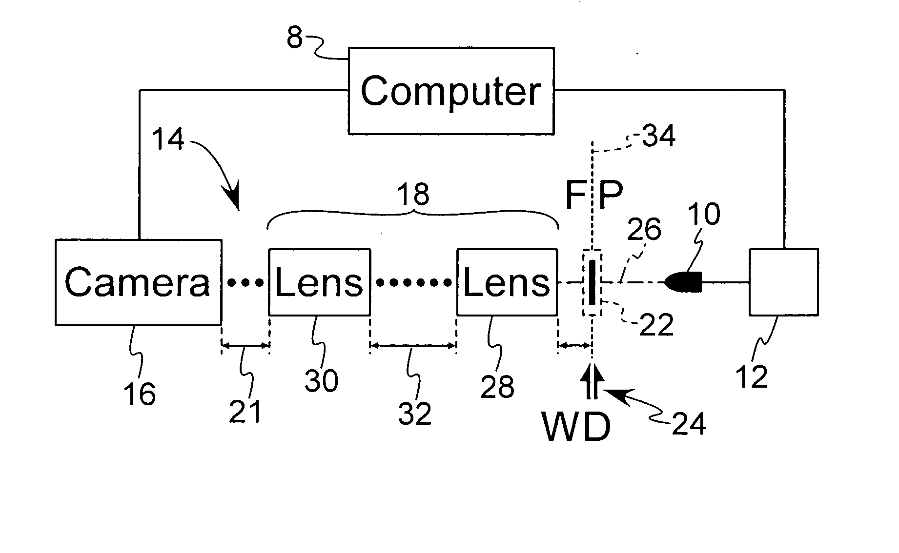
[0028] The method and associated apparatus or system described herein comprises a non-scattering particle image velocimetry (PIV) technique for detecting particle displacement as a function of time in order to obtain velocity and acceleration measurement information from a fluid flow. In particular, the following description is directed to a method of detecting particle and / or particle ensemble locations within a fluid flow with reference to shadows defined by the particles as they are illuminated by a light source, defined herein as particle shadow velocimetry (PSV).

[0029] Referring to FIG. 1, an optical setup for performing the present method is illustrated diagrammatically and includes a light source 10, a pulser 12 for powering the light source 10 at a predetermined pulse rate, and an image detecting system 14 comprising a camera 16, connected to a lens element or lens system 18 wherein the spacing 21 between the lens system 48 and the camera 16 may be adjusted. A computer 8 ma...


PUM


Abstract

A method of measuring fluid flow including the steps of providing a light source including at least one LED, providing an image detecting element and defining an illuminated measurement space with an optical element located between the measurement space and the image detecting element. The measurement space is located optically in-line between the light source and the image detecting element. The method further includes the steps of providing a fluid flow through the measurement space, the fluid flow including particles, and illuminating the measurement space with the light source to induce light extinction from the particles comprising shadow markers of the position of the particles within the fluid flow. The image detecting element is used to detect the shadow markers produced by the particles to record displacement of the particles as a function of time corresponding to movement of the fluid flow. In a further aspect, the light source includes plural LEDs emitting different colors.

Description


Claims


Application Information

Patent Timeline
Owner INNOVATIVE SCI SOLUTIONS
Why Eureka
Try Eureka