Speaker and method for manufacturing the speaker

Inactive Publication Date: 2006-08-10
CITIZEN ELECTRONICS CO LTD
View PDF3 Cites 12 Cited by
  • Summary
  • Abstract
  • Description
  • Claims
  • Application Information

AI Technical Summary

Benefits of technology

[0015] Conventionally, an outer yoke, a magnetic element, and an inner yoke are interconnected by means of an adhesive. According to the present invention, the outer yoke, the magnetic element and the

Problems solved by technology

This leads to reduction of the number of molding steps and thus, of the production cost of the s

Method used


Image

  • Speaker and method for manufacturing the speaker
  • Speaker and method for manufacturing the speaker
  • Speaker and method for manufacturing the speaker

Examples


Embodiment Construction

[0041] The present invention will now be described with reference to the accompanying drawings.

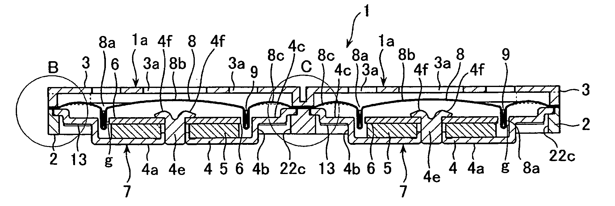
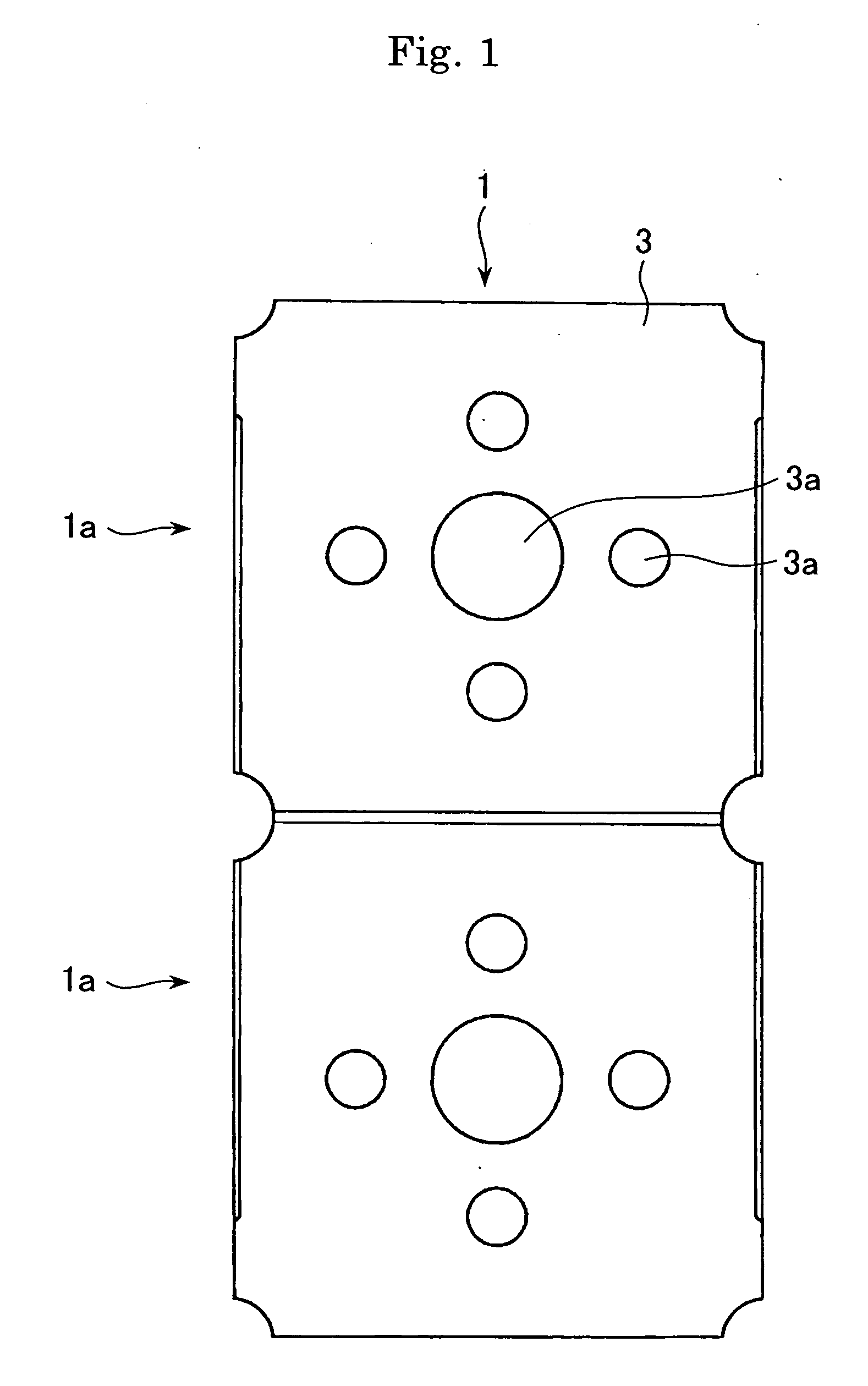
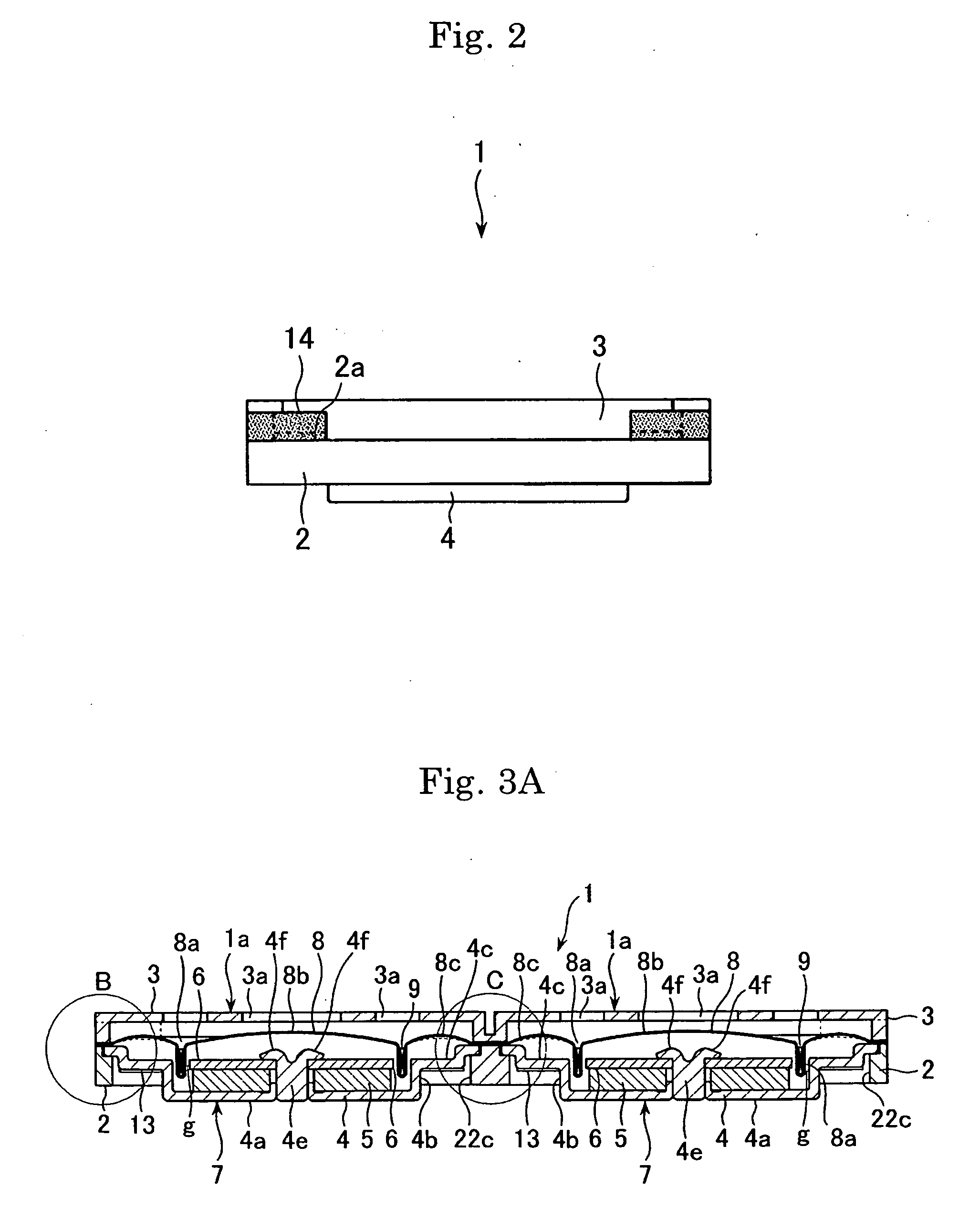
[0042] Referring now to FIGS. 1 to 4, there is illustrated a speaker 1 made according to the present invention. A specific method for manufacturing the speaker 1 is illustrated in FIGS. 5 to 17 and will later be described in detail. The speaker 1 includes two independent acoustic transducers or speaker units 1a, 1a.

[0043] As shown better in FIGS. 3 and 4, each of the speaker units 1a, 1a has a generally square frame 2 having a circular receptacle opening 22c, a magnetic circuit unit 7 arranged in the receptacle opening 22c and composed of a pan-shaped outer yoke 4, a magnetic element 5, a top plate or inner yoke 6, a voice coil 9 inserted into a magnetic gap g formed in the magnetic circuit unit 7, a moving diaphragm 8 attached to the voice coil 9, a protective member 3 mounted on the frame 2 to protect the diaphragm 8 and having sound holes 3a, 3a, and a rear mesh 13 as a dust cover. Th...


PUM


Abstract

A method of manufacturing a speaker includes providing an integral set of frames each with a receptacle opening, mounting a plurality of magnetic circuit units in the respective receptacle openings of the integral set of frames, mounting an integral set of diaphragms to the integral set of frames with diaphragms aligned with respective frames, mounting a plurality of voice coils to the integral set of diaphragms with the voice coils operatively connected to the respective magnetic circuit units to form an integral set of speaker units each comprising the frame, the magnetic circuit unit, the diaphragm and the voice coil, and dividing the integral set of speakers into individual speakers each with at least one speaker unit.

Description

[0001] This application claims priority under 35 U.S.C. § 119 to Japanese Patent Application No. 2005-033682 filed Feb. 9, 2005, the entire content of which is hereby incorporated by reference. FIELD OF THE INVENTION [0002] The present invention generally relates to a micro speaker (hereinafter, simply referred to as a “speaker”) for use in a cellular phone and other devices and a method for manufacturing this kind of speaker. BACKGROUND OF THE INVENTION [0003] An electroacoustic transducer or speaker is incorporated into, for example, a cellular phone as shown in Japanese patent application publication No. 2003-143676. Traditionally, speakers of this kind speaker is manufactured on a one-by-one basis. Attempts have been made to manufacture a speaker on a mass production basis, but such attempts were inefficient and unable to reduce the cost of manufacture and provide high yields. [0004] It is, therefore, an object of the present invention to make it possible to more efficiently man...

Claims


Application Information

Patent Timeline
IPC IPC(8): H04R9/06H04R1/00H04R11/02
CPCH04R31/00H04R9/045
Inventor OHTA, YOSHIZUMI
Owner CITIZEN ELECTRONICS CO LTD
Why Eureka
Try Eureka