Liquid filter system

a filter system and liquid filter technology, applied in the direction of filter cartridge filters, filtration separation, separation processes, etc., can solve the problems of contaminated immediate surroundings of oil filter elements, difficulty in separating various materials for disposal, and changing filter elements, etc., to facilitate the removal of filter elements and facilitate the effect of removal

Inactive Publication Date: 2006-08-17
MANN HUMMEL GMBH
View PDF9 Cites 55 Cited by
  • Summary
  • Abstract
  • Description
  • Claims
  • Application Information

AI Technical Summary

Benefits of technology

The present invention relates to an improved design for removing a filter element from a housing. The filter element has a fold-down handle attached to the outer edge of the canister. The handle consists of flexible semi-circular parts connected by a hinge, making it easy to hold onto when replacing the filter. The invention allows for proper alignment between the filter element and the attachment points while still absorbing any axial force caused by the high pressure drop across the filter.

Problems solved by technology

The technical problem addressed in this patent is related to improving the design of liquid filter systems such as oil filters for internal combustion engines. Current designs have limitations including the difficulty in separating different materials for disposal when using spin-on filters, the high cost associated with replacing entire components instead of just the filter elements when using oil modules, and potential health risks due to handling the oily filter elements. Additionally, current designs make it difficult to determine if the filter element is properly installed.

Method used


Image

  • Liquid filter system
  • Liquid filter system
  • Liquid filter system

Examples


Embodiment Construction

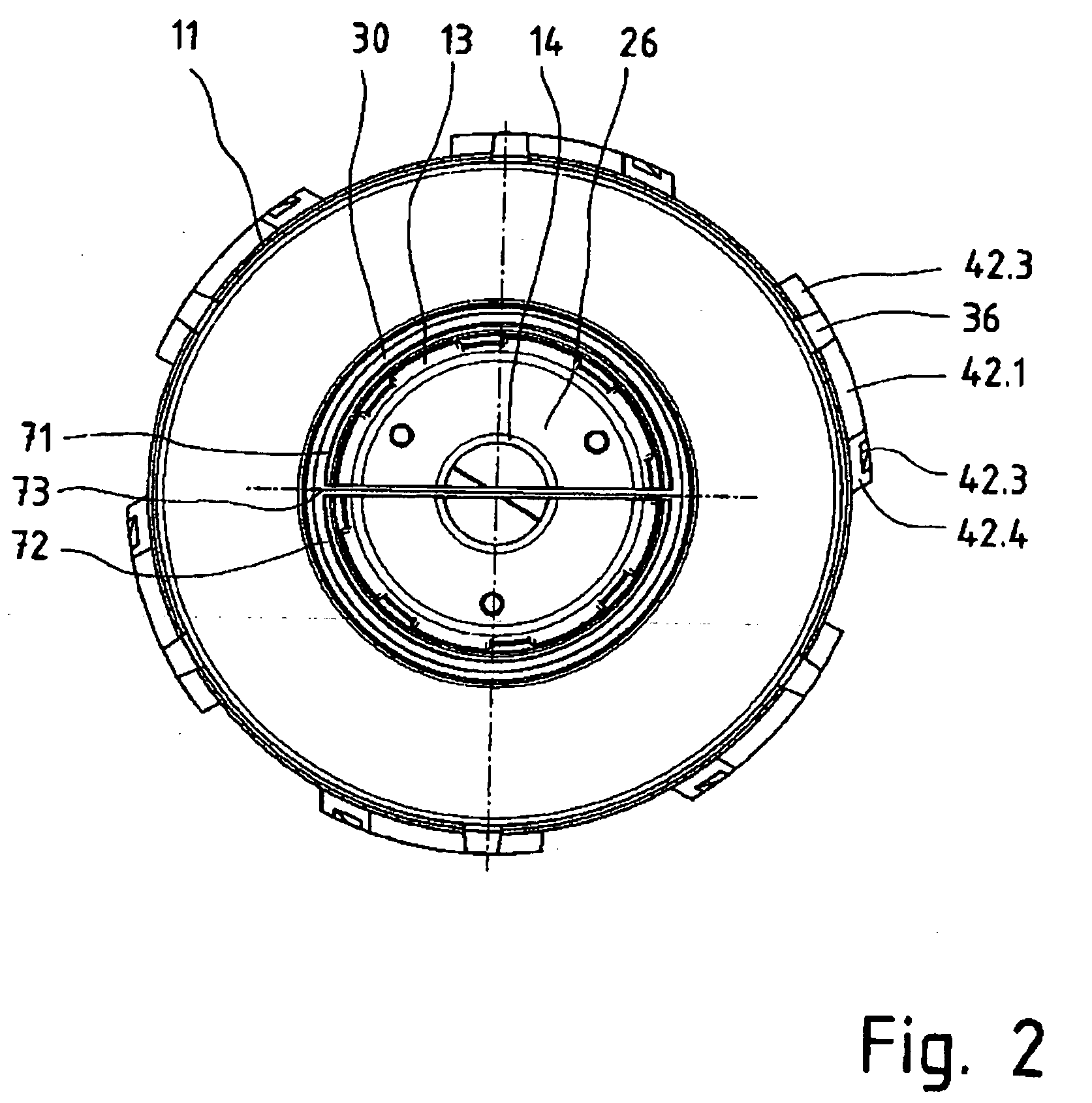
[0034]FIG. 4 shows a housing 11 for the filter system according to the invention, which is substantially pot-shaped or cup-shaped. A bottom edge 11.1, shown pointing upwardly in FIG. 4, has a plurality of axially extending recesses 43 around its circumference. In the illustrated embodiment, a total of six first interlocking elements 42 are arranged near the bottom edge of the housing 11 and distributed around its outer circumference. The recesses 43 each extend far enough in the axial direction to interrupt or split the first interlocking elements 42. Thus, the first interlocking elements 42 are divided by the recesses 43 into partial areas 42.1 and 42.2. An inclined ramp or cam surface 42.4 is formed on the partial area 42.1.

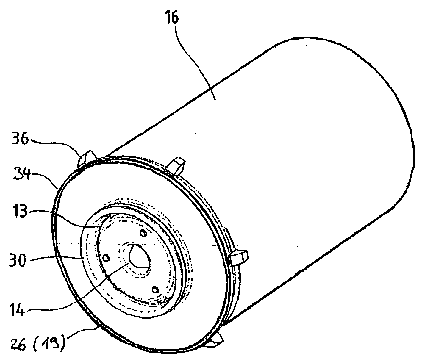
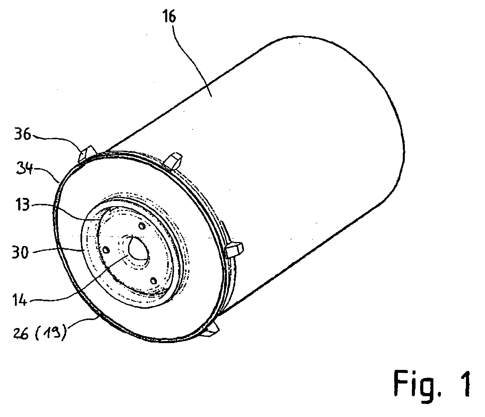
[0035]FIG. 1 shows a bottom view of the filter element 19 with an annular closure face 26. A central support tube 14 is disposed in the center, which also acts as an inlet to the filter element 19. The liquid can flow out again through outlet openings 13, whic...


PUM

PropertyMeasurementUnit
Diameteraaaaaaaaaa
Circumferenceaaaaaaaaaa

Abstract

An oil filter for an internal combustion engine with a cup-shaped housing that is releasably connectable to a receiving head. The housing has a first interlocking element that extends across at least a portion of the outer circumference of the housing and is interrupted by at least one axially extending recess. The filter element has a liquid-tight canister provided on its outer surface with second interlocking elements, which fit into the recesses of corresponding first interlocking elements when the filter element is installed in the housing.

Description


Claims


Application Information

Patent Timeline
Owner MANN HUMMEL GMBH
Why Eureka
Try Eureka