
Adaptive coding and modulation

a technology applied in the field of control of adaptive coding and modulation, can solve the problems of channel quality often changing significantly, loss of data, and need for retransmission of all data, and achieve the effect of higher modulation levels

Inactive Publication Date: 2006-08-17
APPLE INC
View PDF22 Cites 38 Cited by
  • Summary
  • Abstract
  • Description
  • Claims
  • Application Information

AI Technical Summary

Benefits of technology

This approach optimizes data transmission rates by maximizing the use of instantaneous channel capacity without relying on obsolete channel quality estimates, minimizing delays and complexity, and ensuring efficient retransmission of lost data.

Problems solved by technology

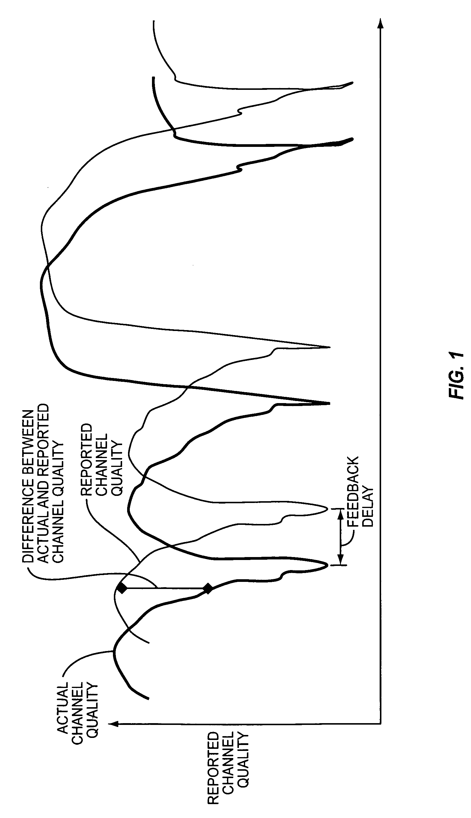
Unfortunately, channel quality often changes significantly in a short period of time, and the time necessary to estimate channel quality, feed these estimates back to the transmitter, and allow the transmitter to react, injects a delay in the feedback sufficient enough to make the channel quality estimates obsolete in many instances.
For example, if a high quality channel quickly degrades to a significant extent, the transmitter may rely on the high channel quality estimates provided by the receiver and select a coding and modulation scheme substantially incompatible with the recently degraded channel.
The result is lost data and the need for retransmission of all data.
The delay associated with the feedback may result in significant differences between the actual and reported channel qualities, as noted above.
In addition to the unreliability of channel quality estimates fed back from a receiver due to delay, there is significant complexity associated with accurately measuring channel quality and providing channel quality estimates to the transmitter.
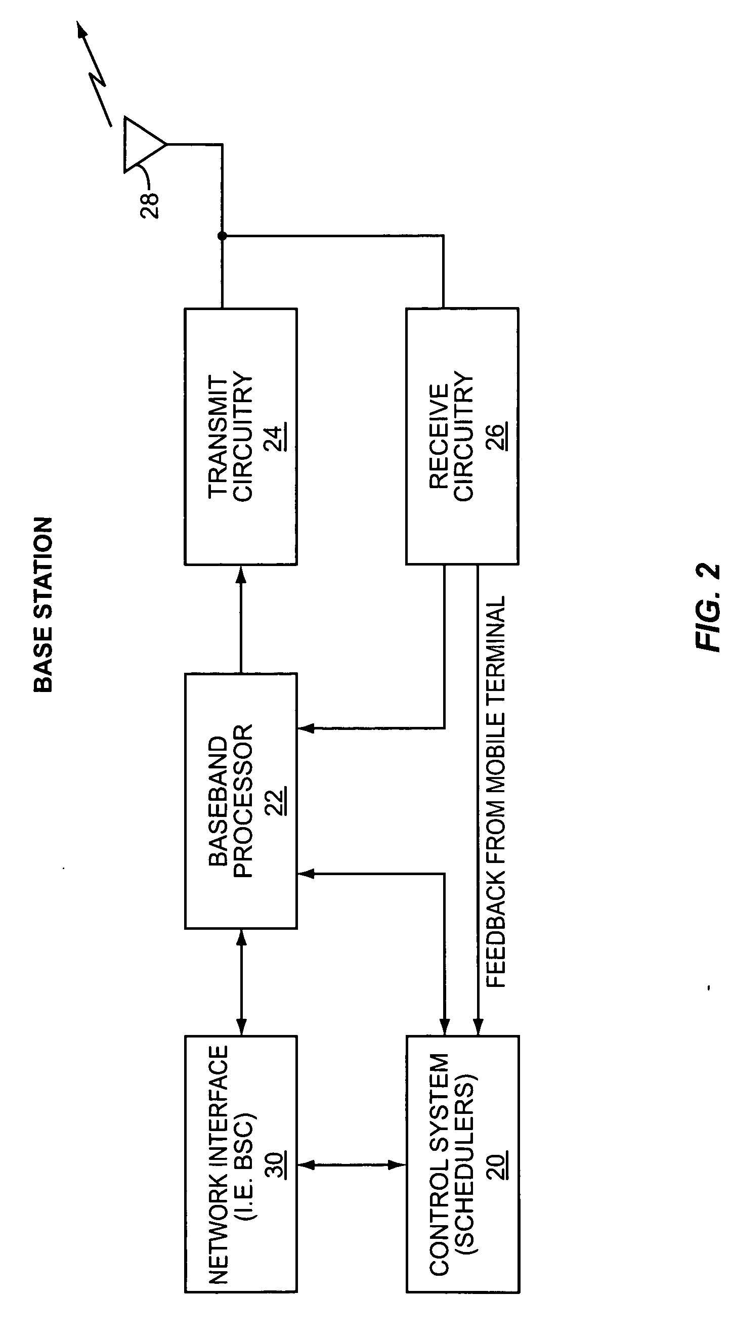
When channel quality estimates are determined for the forward link from a base station to a mobile terminal, the reverse link design for providing channel quality estimates and feeding these estimates back to the base station adds complexity and cost to the design of the mobile terminal and the base station.

Method used


Image

  • Adaptive coding and modulation
  • Adaptive coding and modulation
  • Adaptive coding and modulation

Examples


Embodiment Construction

[0018] The embodiments set forth below represent the necessary information to enable those skilled in the art to practice the invention and illustrate the best mode of practicing the invention. Upon reading the following description in light of the accompanying drawing figures, those skilled in the art will understand the concepts of the invention and will recognize applications of these concepts not particularly addressed herein. It should be understood that these concepts and applications fall within the scope of the disclosure and the accompanying claims.

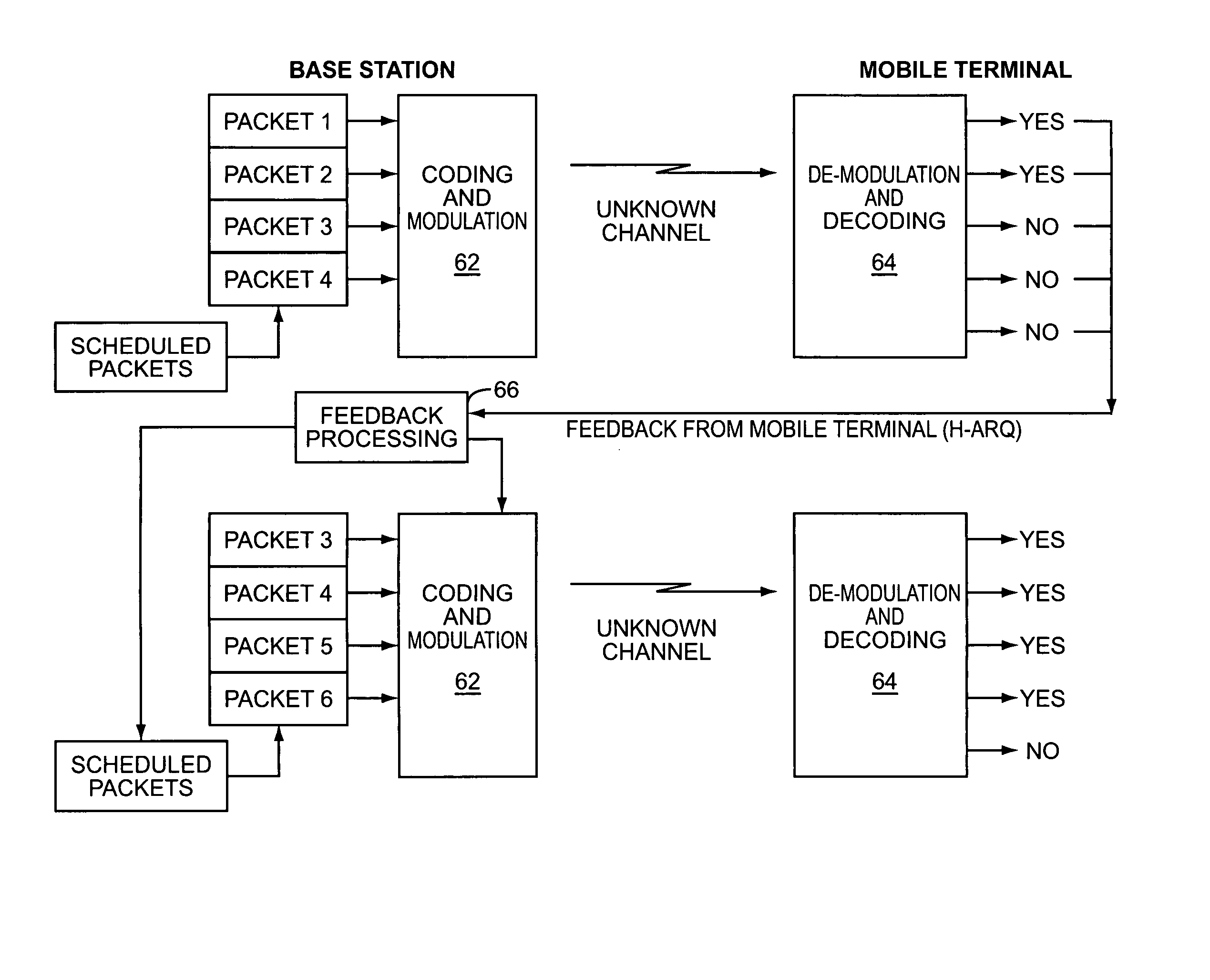
[0019] The present invention eliminates, or at least minimizes, the need for a receiver to transmit channel quality information to the transmitter to allow the transmitter to control coding and modulation schemes. Instead of relying on channel quality information fed back from the receiver, the transmitter hierarchically layers data at ever-increasing coding rates and higher speed modulation techniques. In essence, the transmiss...


PUM


Abstract

The present invention provides a unique feedback system in a wireless communication system wherein the transmission channel is always overloaded with data, which is configured and modulated at a select order of modulation. Based on the channel conditions, only a portion of the data can be successfully received. As such, the receiver will attempt to receive the data using demodulation techniques corresponding to the different levels of modulation used to encode the data transmitted. The receiver will determine the data that is recovered, or the highest order of modulation at which the data is recovered, and provide feedback to the transmitter. The transmitter will then retransmit the data that was not properly received. By overloading the channel at all times, the maximum amount of data capable of being transmitted over the channel is optimized without requiring or heavily relying on the receiver feeding back channel condition information to the transmitter.

Description

[0001] This application claims the benefit of provisional application Ser. No. 60 / 296,099, filed Jun. 5, 2001, the disclosure of which is hereby incorporated by reference in its entirety.FIELD OF THE INVENTION [0002] The present invention relates to controlling adaptive coding and modulation in wireless communication environments, and in particular to providing such control without relying on channel quality estimates. BACKGROUND OF THE INVENTION [0003] Many wireless communication systems dynamically change coding and modulation techniques in an effort to maximize data rates in light of changing channel conditions. In general, data rates decrease and the coding and modulation techniques are more robust as channel conditions degrade, and vice versa. Traditionally, coding and modulation schemes for transmission have been controlled based on channel quality estimates measured at a receiver and fed back to the transmitter. Unfortunately, channel quality often changes significantly in a ...

Claims


Application Information

Patent Timeline
Patent Type & Authority Applications(United States)
IPC IPC(8): H04L12/26H04L1/00H04L1/18H04L27/00
CPCH04L1/0003H04L1/0009H04L1/0068H04L1/1854H04L1/1887H04L27/0012H04L1/18
Inventor ZHU, PEIYINGTONG, WENROYER, CLAUDE C.
Owner APPLE INC
Learn More