

Electronic camera
a technology of electronic cameras and cameras, applied in the field of electronic cameras, can solve the problems of low stability of focusing operation, confusion of users, and eye focusing, and achieve the effect of focusing on a person
- Summary
- Abstract
- Description
- Claims
- Application Information
AI Technical Summary
Benefits of technology
Problems solved by technology
Method used
Image

Examples
first embodiment
Configuration of First Embodiment
[0048] First, the configuration of an electronic camera 1 according to a first embodiment of the present invention will be described.
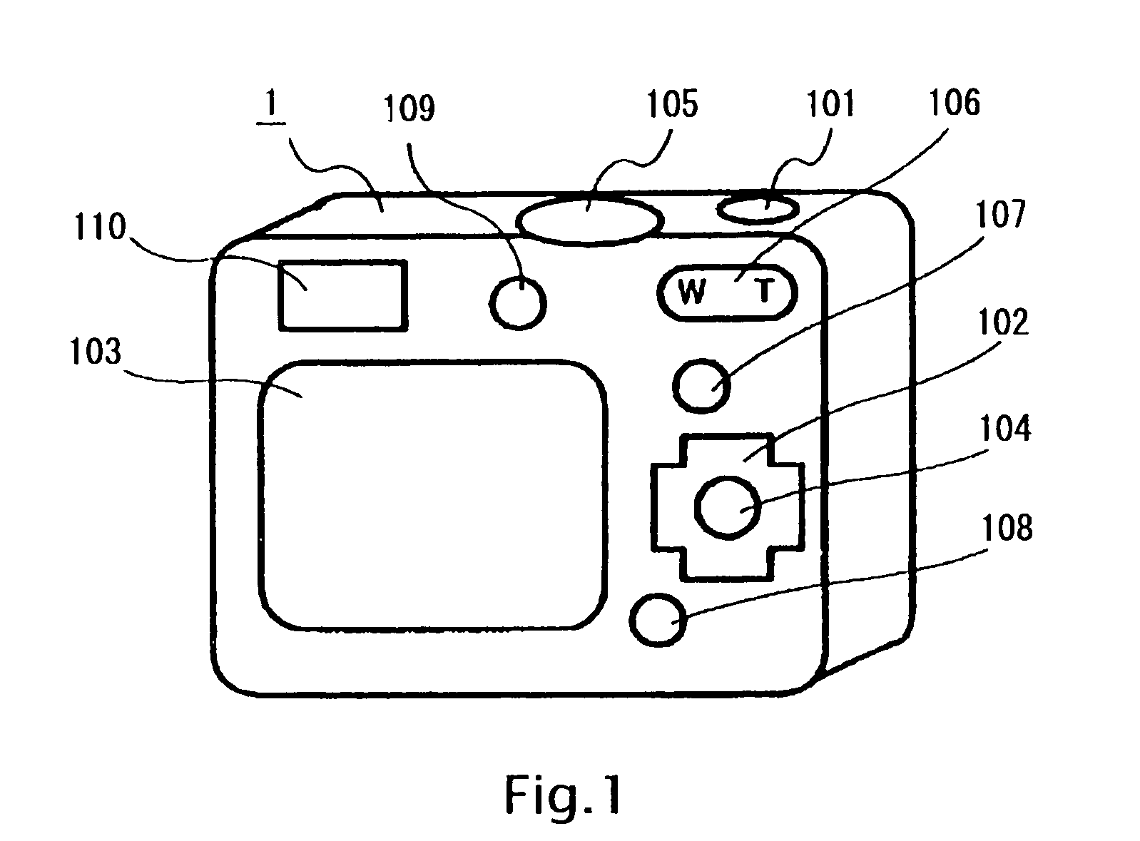
[0049]FIG. 1 is an external view of the electronic camera 1 according to the first embodiment. In FIG. 1, the electronic camera 1 includes a release button 101, a cruciform key 102, a monitor 103, a decision button 104, a mode select dial 105, a zoom button, 106, a menu button 107, a play button 108, a closeup shooting button 109, and an optical viewfinder 110.
[0050] The release button 101 is a button capable of detecting two-stage operations: a half-press stage and a full-press stage. The release button 101 is manipulated by a user when the user instructs the start of shooting. The cruciform key 102 is manipulated by the user to move a cursor or the like on the monitor 103. The decision button 104 is a button manipulated by the user when the user selects and decides an item with the cruciform key 102 or the like. The...
second embodiment
Description of Second Embodiment
[0088]FIG. 15 is a block diagram showing an overview of an electronic camera of a second embodiment. The electronic camera of the second embodiment includes a shooting lens 11, lens driving mechanisms 12, an image pickup device 13, an analog signal processing section 14, an A / D conversion section 15, an image processing section 16, a compression / decompression section 17, a memory 18, a card I / F 19, a monitor I / F 20 and a liquid crystal display 21, a manipulation section 22, a CPU 23, and a bus 24. Incidentally, the image processing section 16, the compression / decompression section 17, the memory 18, the card I / F 19, the monitor I / F 20, and the CPU 23 are connected respectively via the bus 24.
[0089] The shooting lens 11 is composed of a group of plural lenses including a focusing lens for adjusting the focusing position. The position of this shooing lens 11 in an optical axis direction is adjusted by the lens driving mechanisms 12.
[0090] The image pi...
third embodiment
Description of Third Embodiment
[0122]FIG. 19 is a block diagram showing an overview of an electronic camera of a third embodiment. In the description of the following embodiments, the same numerals and symbols are used to designate components common to the second embodiment, and a description thereof will be omitted.
[0123] The third embodiment is a modified example of the second embodiment, and its configuration differs from that of the second embodiment in that an attitude sensor 26 is connected to the CPU 23. The attitude sensor 26 detects a shooting attitude in which the electronic camera is held in a normal position, an upper right vertical position shooting attitude in which the right side of the electronic camera is located at an upper position, an upper light vertical shooting attitude in which the left side of the electronic camera is located at an upper position, and an inverted position shooting attitude in which the electronic camera is inverted. When the focusing positi...
PUM
 Abstract
Description
Claims
Application Information