This helps you quickly interpret patents by identifying the three key elements:
Problems solved by technology
Method used
Benefits of technology
Benefits of technology
[0012] It is also an object of the invention to provide an image forming apparatus and an optional sheet feeding device in which the separating hook is unlikely to be damaged.
[0033] Therefore, such phenomenon that the sheets of the recording media which are contained inside the apparatus may rapidly move toward the separating hook due to a shock at the time of placing the apparatus on the installation face, thereby colliding with the separating hook will be unlikely to happen. As a result, probability that the separating hook may be damaged with the collision will be advantageously decreased.
[0046] Therefore, such phenomenon that the sheets of the recording media which are contained inside the apparatus may rapidly move toward the separating hook due to a shock at the time of placing the apparatus on the installation face, thereby colliding with the separating hook will be unlikely to happen regardless of the position where the center of gravity for the apparatus is. As a result, the probability that the separating hook may be damaged with the collision will be advantageously decreased.
Problems solved by technology
In the image forming apparatus, in which the handles for lifting the apparatus are provided at the same level, there is such a problem that in a case where two persons, for example, lift and carry the apparatus, a larger weight is exerted on the person who handles the handle at the side where the center of gravity is biased.
There is also the same problem described above in the sheet feeding device which is adapted to be attached to the image forming apparatus to feed a recording medium thereto, and to store recording media.
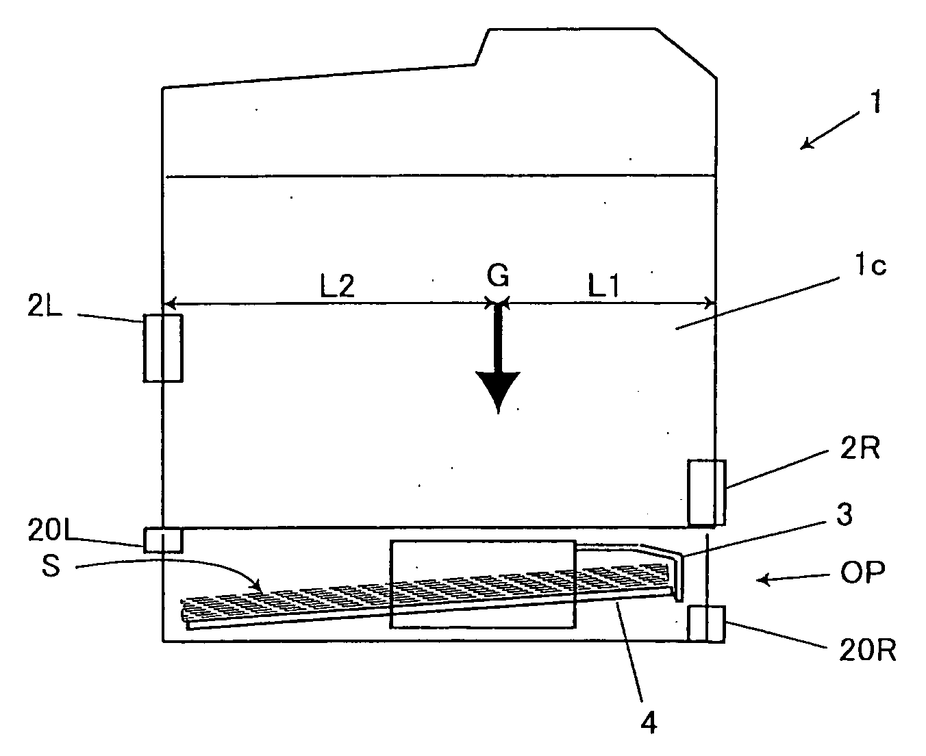
Therefore, in a case where the accuracies in its shape and position become out of order, receiving the impact of the recording media S, recording media S may not be properly separated, and that the recording medium S may not be fed to a proper position of the main body 1c of the image forming apparatus.
Method used
Image
Click on the blue label to locate the original text in one second.
Reading with bidirectional positioning of images and text.
Examples
first embodiment
[0054] Embodiments of the invention will be described below in detail with reference to the accompanying drawings.
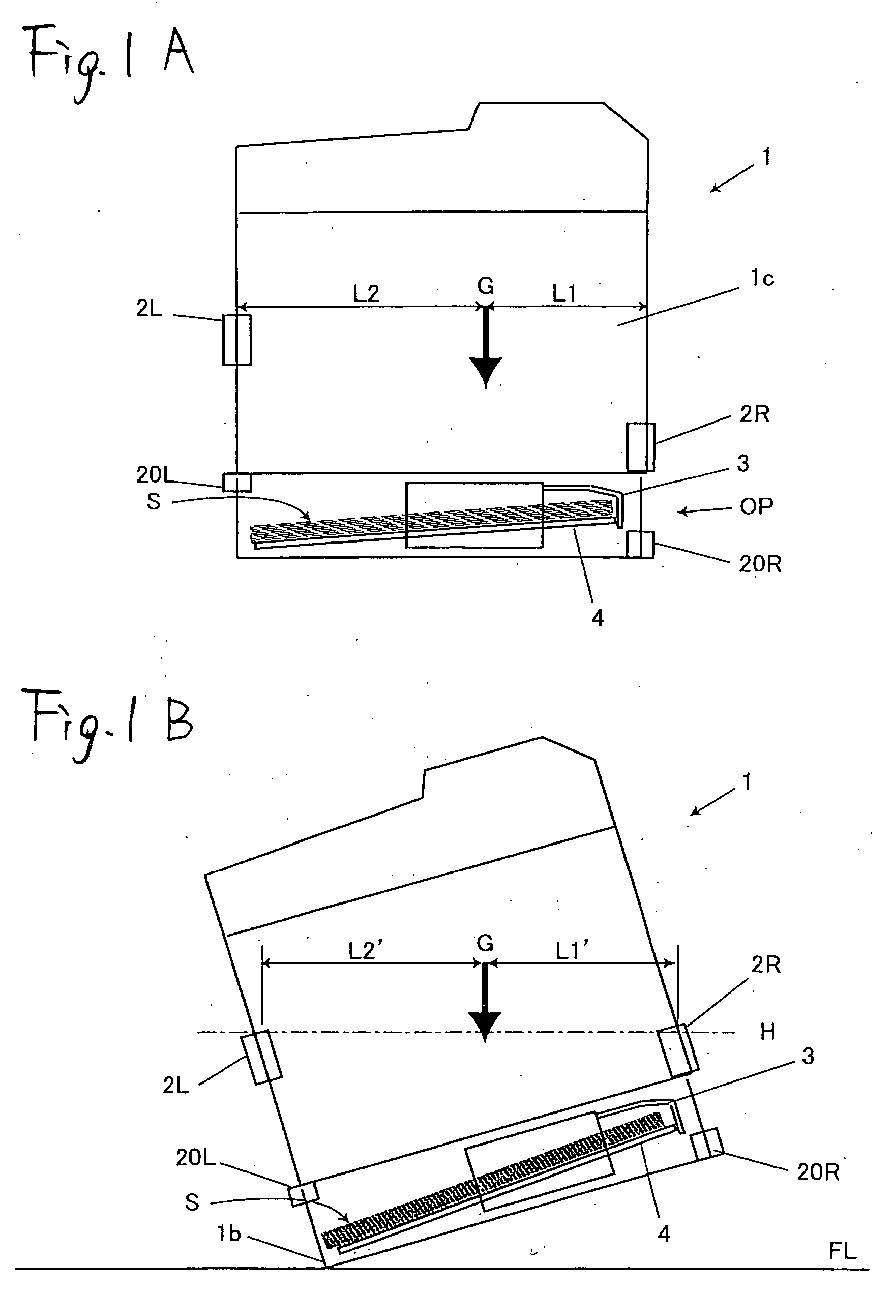
[0055] As shown in FIG. 1A, an image forming apparatus 1 according to a first embodiment of the invention has a center of gravity G which is biased to the right in a horizontal direction. Handles 2R and 2L for lifting the apparatus are respectively provided at the right and left side of the apparatus.
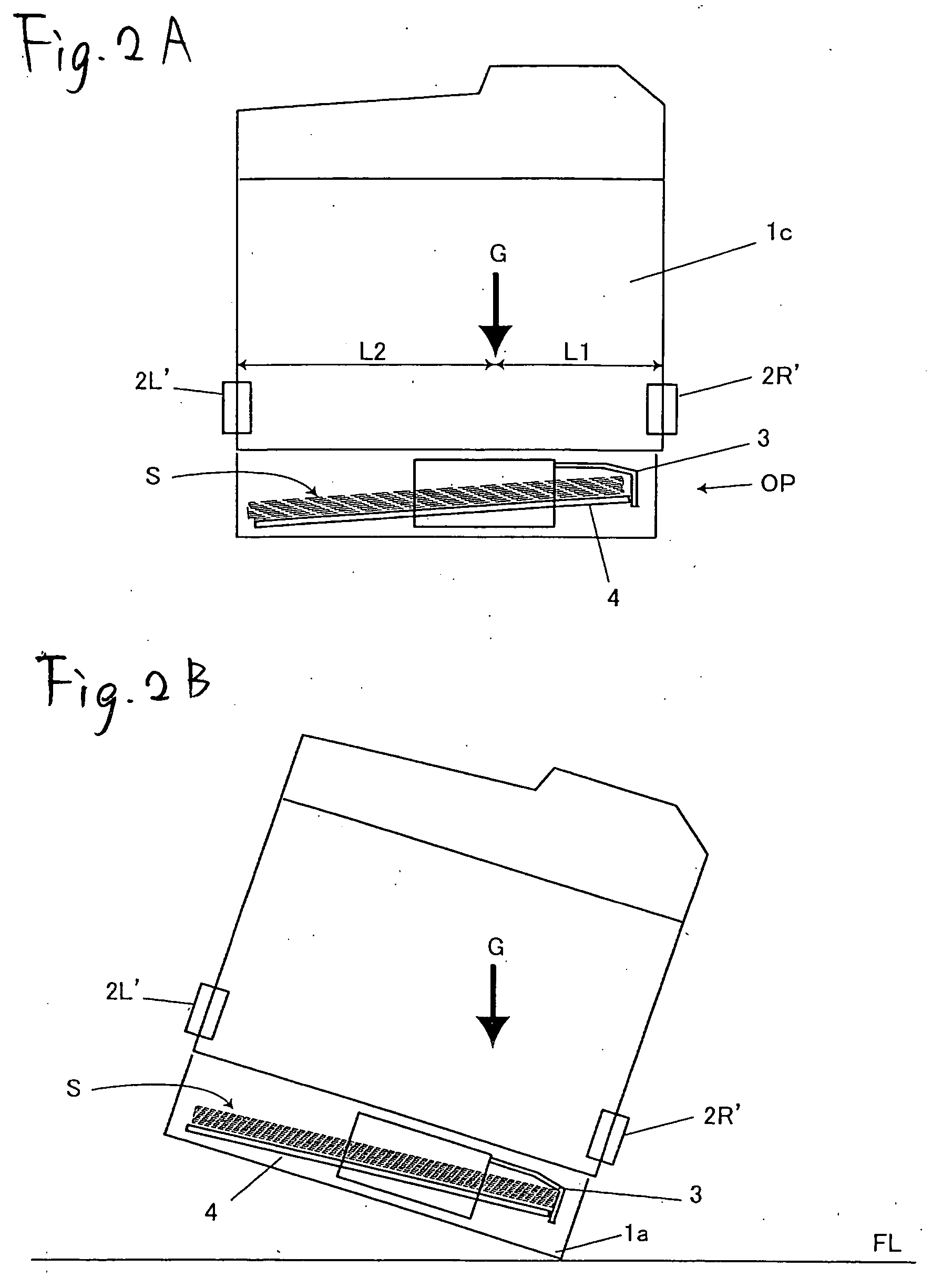
[0056] In the apparatus of this type, provided that the handles 2L′, 2R′ are provided at the same level as shown in FIG. 2A, in a case where two persons lift and carry the apparatus with these handles, a larger weight will be exerted on the person at the side where the center of gravity G is biased, that is, the person who handles the right handle 2R′, in this case.
[0057] There is also the same problem described above in the sheet feeding device OP which is adapted to be attached to the image forming apparatus 1 to feed a recording medium S thereto, and to store recording...
second embodiment
[0065] Next, a second embodiment of the invention will be described. Components similar to those in the first embodiment will be designated by the same reference numerals and repetitive explanations for those will be omitted.
[0066] In the second embodiment, the handle 2R at the side where the separating hook 3 is provided is provided at a lower level than the handle 2L at the opposite side regardless of the center of gravity of the apparatus, as shown in FIG. 3A.
[0067] According to this structure, it will be highly probable that the apparatus 1 may strike the installation face FL from the bottom 1b of the apparatus at the side of the handle 2L which is provided at the higher position, that is, the opposite side to the side where the separating hook 3 is provided regardless of the position where the center of gravity for the apparatus is.
[0068] Therefore, such phenomenon that the sheets of the recording medium S which are contained inside the apparatus 1 may rapidly move toward th...
PUM
Abstract
A second side face opposes to a first face. A first handle is provided on the first side face at a first position and adapted to be used to lift an image forming apparatus. A second handle is provided on the second side face at a second position which is higher than the first position, and adapted to be used to lift the image forming apparatus together with the first handle. A center of gravity for the image forming apparatus is located closer to the first side face than the second side face.
Description
BACKGROUND OF THE INVENTION [0001] The present invention relates to an image forming apparatus such as a printer, a facsimile, a copyingmachine, and a sheet feeding device which is selectively installed in the image forming apparatus as required. [0002] Generally, the image forming apparatus is provided with handles for lifting it, at right and left sides (or in front and back, the case is the same in the following description) of the apparatus. [0003] Japanese Design Registration No. 1183592, for example, discloses an image forming apparatus in which such handles are provided at the same level. [0004] Generally, a center of gravity for the image forming apparatus is rarely positioned at the center in a horizontal direction, but usually biased to the left or to the right. [0005] In the image forming apparatus, in which the handles for lifting the apparatus are provided at the same level, there is such a problem that in a case where two persons, for example, lift and carry the appar...
Claims
Application Information
Patent Timeline
Application Date:The date an application was filed.
Publication Date:The date a patent or application was officially published.
First Publication Date:The earliest publication date of a patent with the same application number.
Issue Date:Publication date of the patent grant document.
PCT Entry Date:The Entry date of PCT National Phase.
Estimated Expiry Date:The statutory expiry date of a patent right according to the Patent Law, and it is the longest term of protection that the patent right can achieve without the termination of the patent right due to other reasons(Term extension factor has been taken into account ).
Invalid Date:Actual expiry date is based on effective date or publication date of legal transaction data of invalid patent.

