
Vehicle door lock device

a vehicle door lock and door lock technology, applied in the direction of passenger lock actuation, carpet fasteners, lock applications, etc., can solve the problems of preventing the improvement of the waterproof property of reducing the sealing ability of the housing b>101/b> for covering the vehicle door lock device,

Inactive Publication Date: 2006-08-24
AISIN SEIKI KK
View PDF5 Cites 35 Cited by
  • Summary
  • Abstract
  • Description
  • Claims
  • Application Information

AI Technical Summary

Benefits of technology

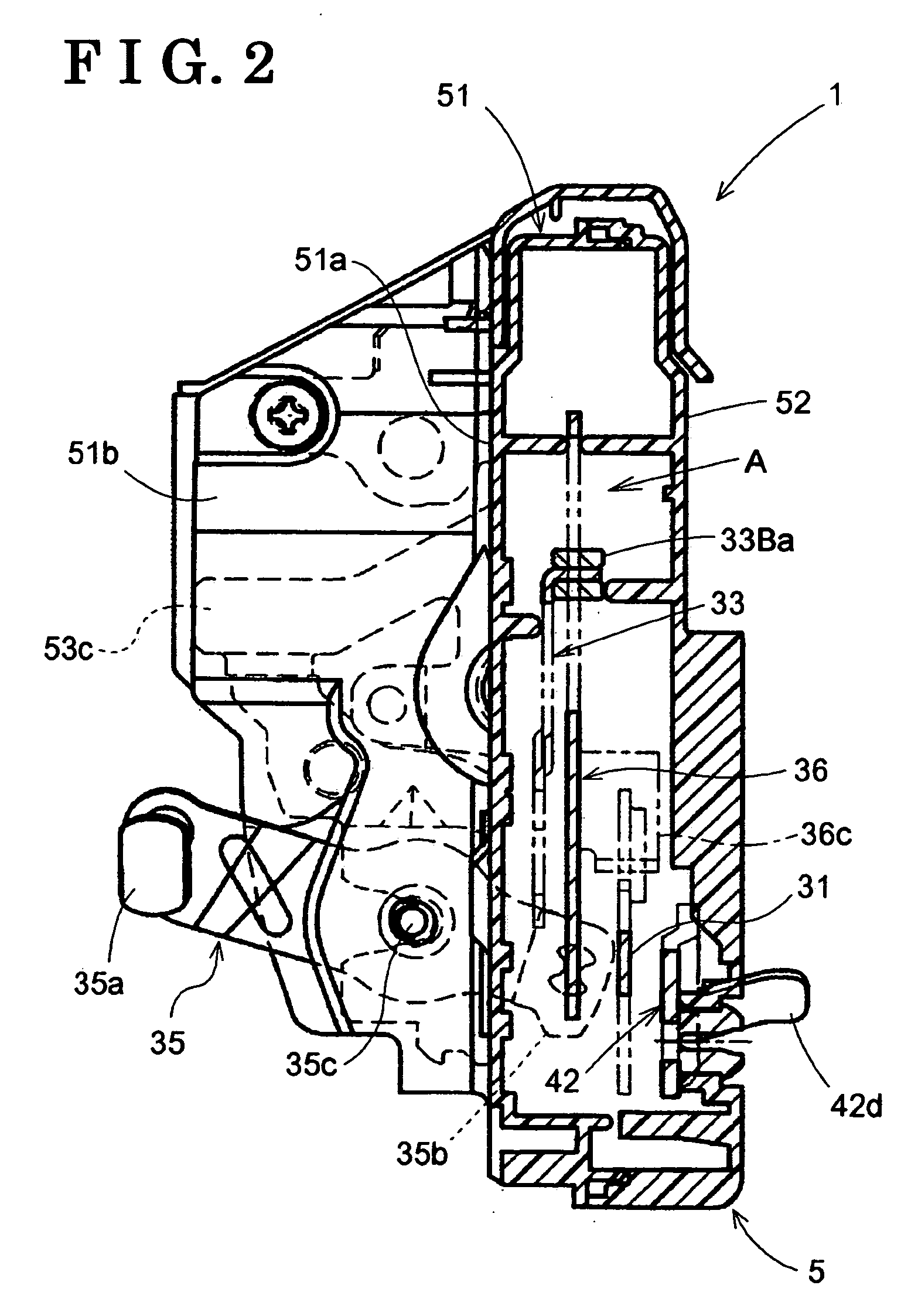
[0009] According to an aspect of the present invention, a vehicle door lock device includes a base member on which a pivot shaft is supported, a first lever rotatably supported on the pivot shaft and linked to a latch mechanism engageable with a striker provided on a vehicle, a second lever rotatably supported on the pivot shaft and operated in association with a door handle, an engaging member supported on the first lever so as to be slidable relative thereto and including an engaging pin for engaging the first lever and the second lever with each other in a predetermined engaging position and disengaging the first lever and the second lever from each other in a predetermined release position displaced from the engaging position, and an operating lever linked to the engaging member and bringing the engaging pin to operate between the engaging position and the release position. The first lever, the second lever, the engaging member, and the operating member are arranged on one side of the base member. The base member includes a restricting projection portion on the one side for restricting a movement of the engaging pin as in the release position in a peripheral direction relative to the pivot shaft.

Problems solved by technology

Accordingly, sealing ability of the housing 101 for covering the vehicle door lock device may be reduced, which may prevent improvement of waterproof property of the vehicle door lock device.

Method used


Image

  • Vehicle door lock device
  • Vehicle door lock device
  • Vehicle door lock device

Examples


Embodiment Construction

[0027] An embodiment of the present invention is explained with reference to the attached drawings. FIG. 13 is a schematic view showing a state in which a vehicle door lock device 1 according to the present embodiment is installed in a vehicle door Y. The vehicle door lock device 1 is arranged so as to face a striker 300 provided on a vehicle body X in cases where the vehicle door Y is closed. The vehicle door Y can be a hinged door, a sliding door, or the like. The vehicle door lock device 1 is connected to an outside door handle 1a and an inside door handle (not shown).

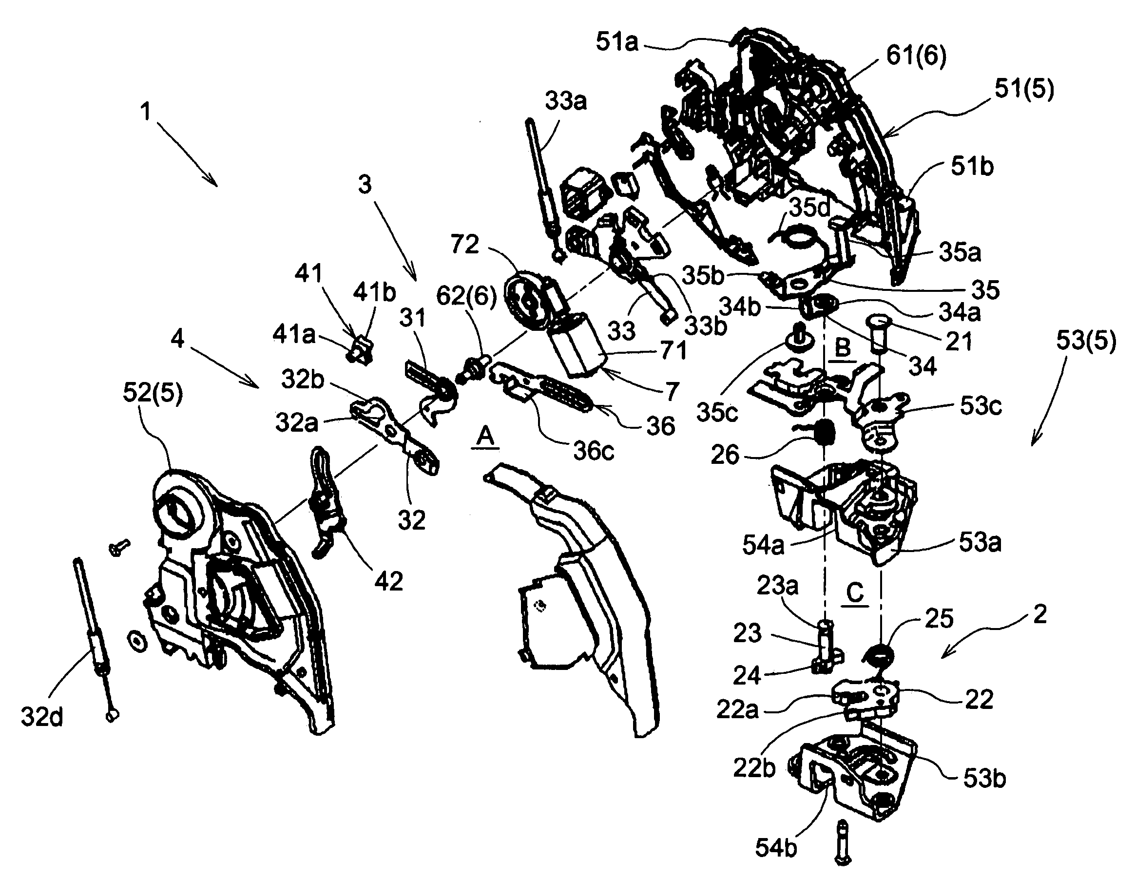
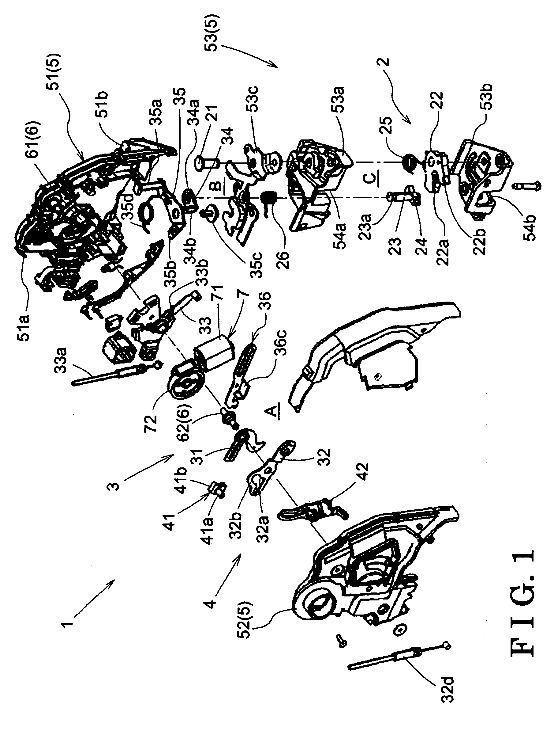
[0028]FIG. 1 is an exploded perspective view of the vehicle door lock device 1 according to the present embodiment. As shown in FIG. 1, the vehicle door lock device 1 includes a latch mechanism 2 for engaging with or disengaging from the striker 300 (see FIG. 13) secured to the vehicle body X so as to bring the vehicle door Y to engage with the vehicle body X, a link mechanism 3 operated in association with an oper...


PUM


Abstract

A vehicle door lock device includes a base member on which a pivot shaft is supported, a first lever rotatably supported on the pivot shaft, a second lever rotatably supported on the pivot shaft and operated in association with a door handle, an engaging member including an engaging pin for engaging the first lever and the second lever with each other in a predetermined engaging position and disengaging from each other in a predetermined release position, and an operating bringing the engaging pin to operate between the engaging position and the release position. The first lever, the second lever, the engaging member, and the operating member are arranged on one side of the base member. The base member includes a restricting projection portion on the one side for restricting a movement of the engaging pin as in the release position in a peripheral direction relative to the pivot shaft.

Description

CROSS REFERENCE TO RELATED APPLICATIONS [0001] This application is based on and claims priority under 35 U.S.C. § 119 to Japanese Patent Application No. 2005-046162, filed on Feb. 22, 2005, the entire content of which is incorporated herein by reference. FIELD OF THE INVENTION [0002] This invention generally relates to a vehicle door lock device. BACKGROUND [0003] A known vehicle door lock device includes a mechanism for prohibiting a release of engagement between a vehicle door and a vehicle body by means of an operation of a door handle. Such the vehicle door lock device is disclosed in JP2003-328623β. The door lock device disclosed is equipped with a child lock mechanism (i.e. a child proof mechanism) for prohibiting a release of engagement between a vehicle door and a vehicle body by means of an operation of an inside handle. [0004] Precisely, as sown in FIG. 14, the vehicle door lock device disclosed includes a housing 101, an inside lever 102 arranged on the housing 101 and op...

Claims


Application Information

Patent Timeline
IPC IPC(8): E05C3/06E05B83/36E05B77/26E05B77/34E05B77/36E05B79/08E05B85/02
CPCE05B77/26Y10S292/23E05B81/06E05B81/16E05B81/34Y10T292/1047
Inventor SUZUMURA, MAKOTOMURAMATSU, AKIRATANABE, SIGERUKUNIMATSU, YUKINOBU
Owner AISIN SEIKI KK
Learn More