Rotary cutting tool having multiple helical cutting edges with differing helix angles

a cutting edge and helix technology, applied in shaping cutters, manufacturing tools, metal working devices, etc., can solve the problems of end mill cutters breaking during use, cutting edges of end mill cutters becoming dull, internal stresses generated in end mill cutters during use increasing,

Active Publication Date: 2006-08-24
CARBIDE GRINDING CO INC +1
View PDF22 Cites 30 Cited by
  • Summary
  • Abstract
  • Description
  • Claims
  • Application Information

AI Technical Summary

Problems solved by technology

Over time, the cutting edges of an end mill cutter become dull due to physical contact between the end mill cutter and workpieces.
As the cutting edges become dull, internal stresses generated within the end mill cutter during use increase.
It is common for end mill cutters to break during use due to the internal stresses.

Method used


Image

  • Rotary cutting tool having multiple helical cutting edges with differing helix angles
  • Rotary cutting tool having multiple helical cutting edges with differing helix angles

Examples


Embodiment Construction

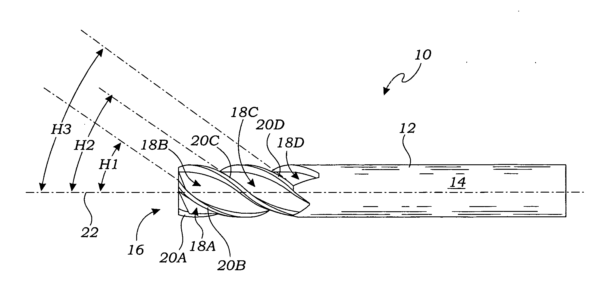
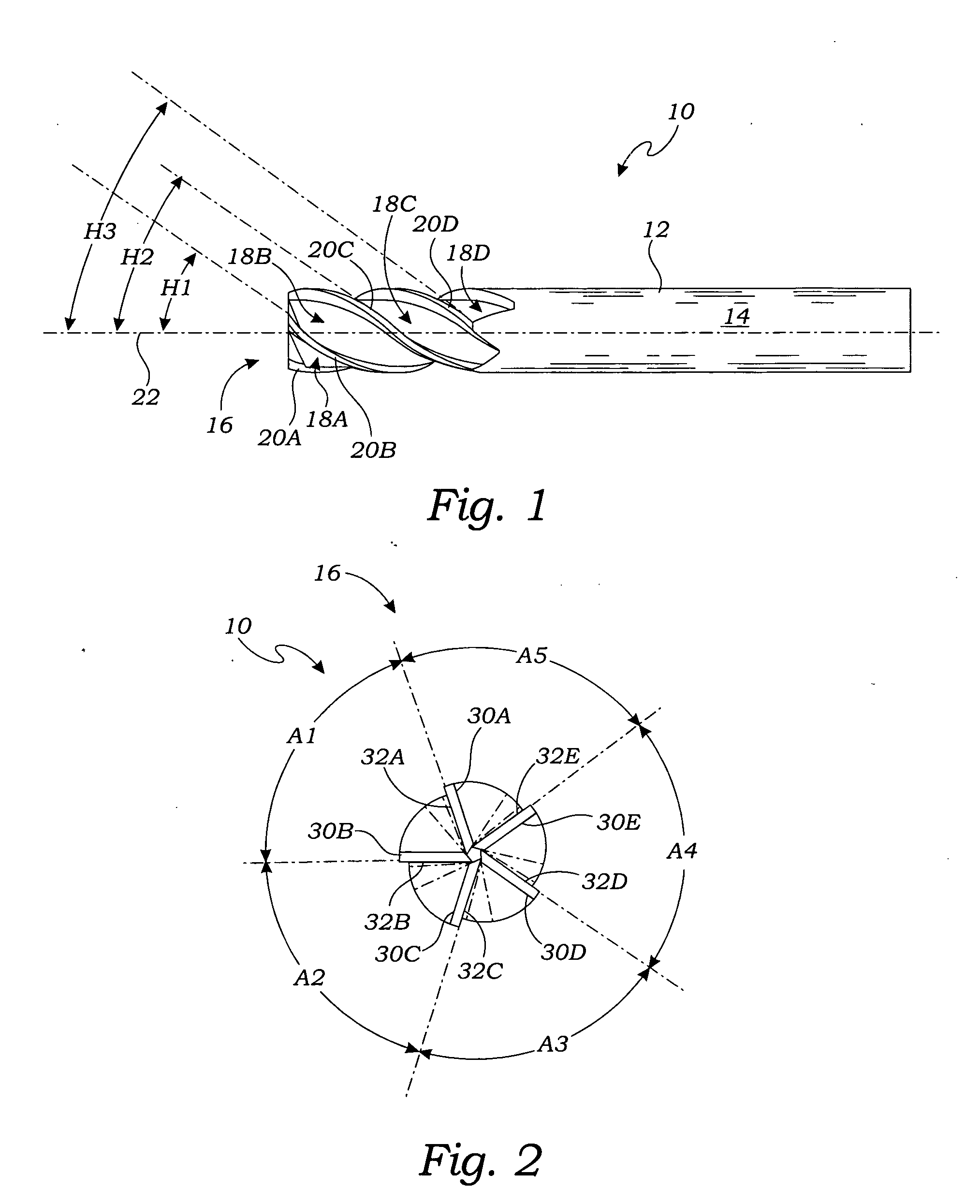
[0022]FIG. 1 is a side elevation view of one embodiment of a rotary cutting tool 10 including a substantially cylindrical main body 12 having a shank portion 14 at one end and a point 16 at an opposite end. In the embodiment of FIG. 1, the rotary cutting tool 10 is an end milling cutter or “end mill,” and has 5 flutes formed in an outer surface of the main body 12. Each of the 5 flutes extends continuously from the point 16 to the shank portion 14, and defines a helical cutting edge about an outer surface of the main body 12. The rotary cutting tool 10 thus has 5 helical cutting edges about the outer surface of the main body 12.

[0023] Four of the 5 flutes of the rotary cutting tool 10 are visible in FIG. 1 and labeled 18A-18D. The flute 18A defines a helical cutting edge 20A about the outer surface of the main body 12. The flute 18B defines a helical cutting edge 20B about the outer surface of the main body 12. Similarly, the flute 18C defines a helical cutting edge 20C about the o...


PUM


Abstract

A rotary cutting tool is disclosed including a substantially cylindrical main body having a shank portion at one end and a point at an opposite end. Five flutes are formed in an outer surface of the main body. Each of the flutes extends continuously from the point to the shank portion, and defines a helical cutting edge having a helix angle between about 32 degrees and approximately 34 degrees with respect to an axis of the main body. At least 2 of the flutes define helical cutting edges having different helix angles.

Description

CROSS-REFERENCE TO RELATED APPLICATIONS [0001] This application for a utility patent claims the benefit of U.S. Provisional Application No. 60 / 654,541, filed Feb. 18, 2005.STATEMENT REGARDING FEDERALLY SPONSORED RESEARCH [0002] Not Applicable BACKGROUND OF THE INVENTION [0003] 1. Field of the Invention [0004] This invention relates generally to rotary cutting tools and end mills, and more particularly to helically fluted end mills having variable helical angles for improved performance characteristics. [0005] 2. Description of Related Art [0006] Rotary cutting tools are used for various machining operations on workpieces. An end mill cutter or “end mill” is a type of rotary cutting tool. Machine operations often carried out using an end mill cutter include the forming of slots, keyways, and pockets. During typical use of an end mill cutter, a milling machine rotatably drives the end mill cutter about its longitudinal axis, and various cutting edges of the end mill cutter are used to...

Claims


Application Information

Patent Timeline
Patent Type & Authority Applications(United States)
IPC IPC(8): B23C5/10
CPCB23C5/003B23C5/10B23C2210/0485B23C2210/0492B23C2210/204Y10T407/196B23C2210/54B23C2228/10B23C2250/16Y10T407/1948Y10T407/1946B23C2210/282
Inventor GREENWOOD, MARK L.CRANKER, KEVIN
Owner CARBIDE GRINDING CO INC
Why Eureka
Try Eureka