Direct tool loading

a technology of automatic material loading and tool loading, which is applied in the direction of thin material handling, packaging, storage devices, etc., can solve the problems of difficult access to the system, and achieve the effect of improving the cleanliness performance and running efficiently

Inactive Publication Date: 2006-08-24
MURATA MASCH LTD
View PDF28 Cites 40 Cited by
  • Summary
  • Abstract
  • Description
  • Claims
  • Application Information

AI Technical Summary

Benefits of technology

[0007] One aspect of the present invention is to provide a transport system to move containers efficiently between a tool and a conveyor. In one embodiment, the present invention provides a load port having a vertically movable kinematic plate. The load port lifts a container, for example, directly off a conveyor—reducing the number of times the container is handled during transport and tool loading.
[0009] Still another aspect of the present invention is to provide a transport and delivery system that is easy to service. OHT systems are located high off the facility floor. Thus, OHT systems are not as easy to access as a floor-based transport system. In one embodiment, a conveyor is mounted to the facility floor. Service personnel can easily access the conveyor for maintenance purposes. In another embodiment, a load port having a two-stage vertical lift for accessing a conveyor located below the facility floor is located completely above the facility floor when the lift is located in a raised position. In this compact stage, the load port can be removed from the tool and lifted over the conveyor.
[0010] Yet another aspect of the present invention is to provide a transport system with safety features. In one embodiment, the present invention includes a safety rail that separates the conveyor from the rest of the facility. The rail provides a barrier to prevent a tool operator from coming into contact with a moving container. Another embodiment of the present invention encloses the conveyor within an isolation tube. The tube also prevents a tool operator from coming into contact with a moving container and, at the same time, may isolate the container or article from the rest of the facility and associated particulate effects. Floor-based transport systems (e.g., conveyor, RGV, AGV) also eliminate the concern that a container will fall from an OHT system and injure an operator.
[0012] Another aspect of the present invention is to provide a container transport and delivery system that improves the cleanliness performance without compromising the integrity of the wafers. In one embodiment, containers are transported along a conveyor that passes below the container plate advance assembly of each load port. In another embodiment, a shuttle transports containers along the facility floor below the datum plane of each load port. In yet another embodiment, containers are transported by an AGV or RGV that travels along the facility floor and passes each load port below the container plate advance assembly. Particles generated by these transport systems fall to the facility floor and do not contaminate wafers being processed by the processing tool.
[0013] Another aspect of the present invention is to provide a transport and delivery system that does not require extensive modifications to the existing process tools, fabrication facility layout or fabrication software in order to run efficiently with existing systems. In one embodiment, the load port secures to the front end of a tool through a BOLTS interface (SEMI Standard E63) or the proposed BOLTS-light standard. The controls, which are typically located in a housing underneath the container plate advance assembly, are relocated inside the load port. Thus, a processing tool does not have to be modified at all to accommodate a load port according to the present invention.

Problems solved by technology

Thus, OHT systems are not as easy to access as a floor-based transport system.

Method used


Image

  • Direct tool loading
  • Direct tool loading
  • Direct tool loading

Examples


Embodiment Construction

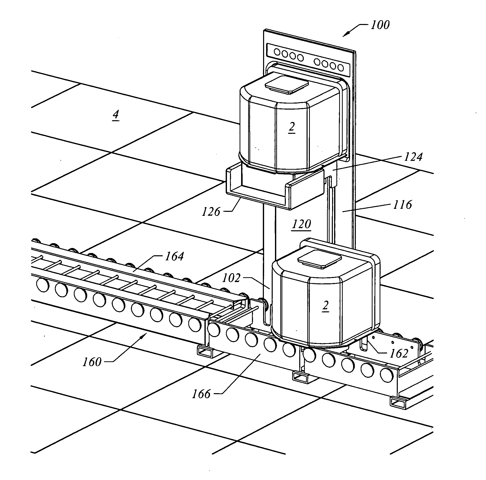
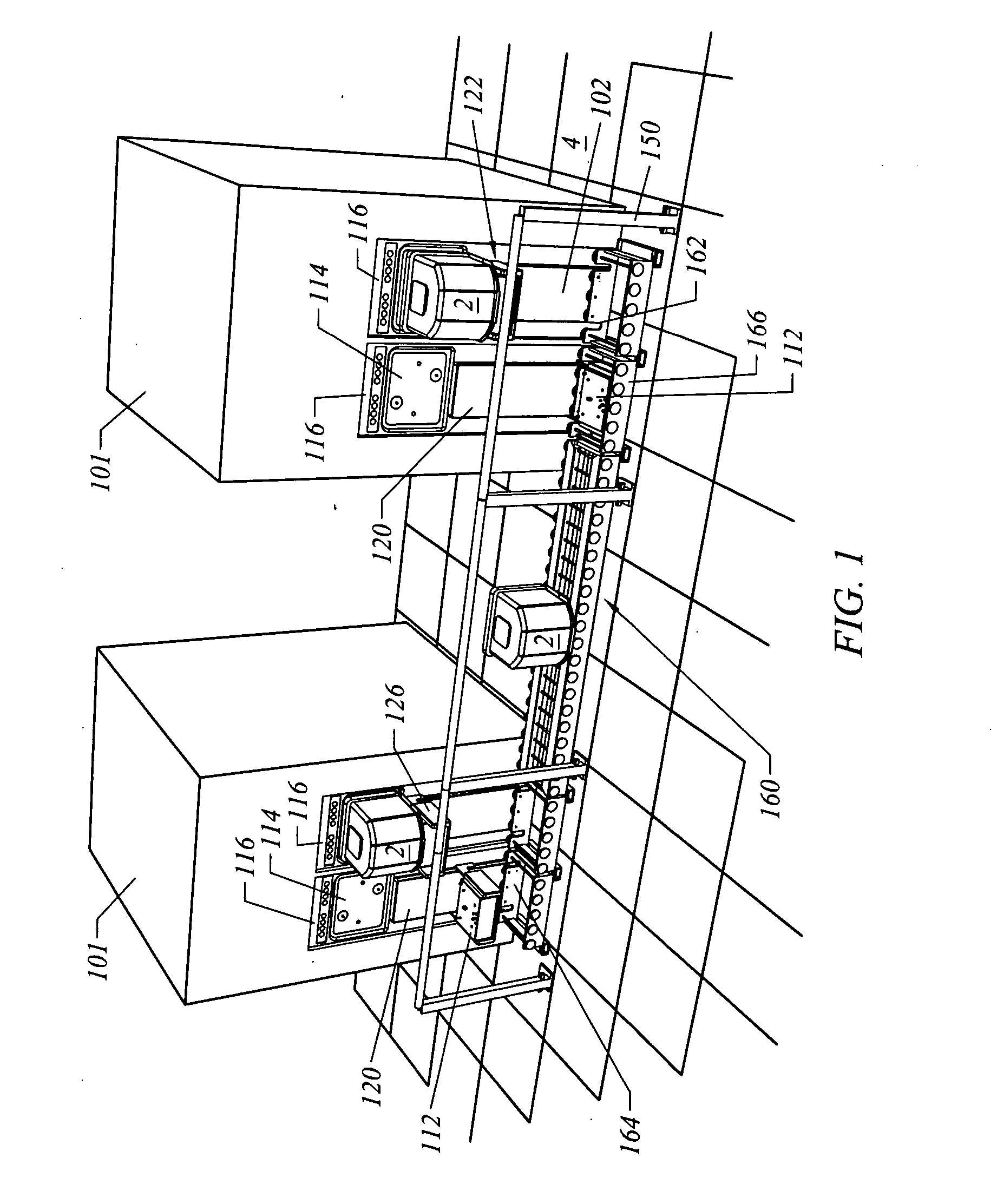
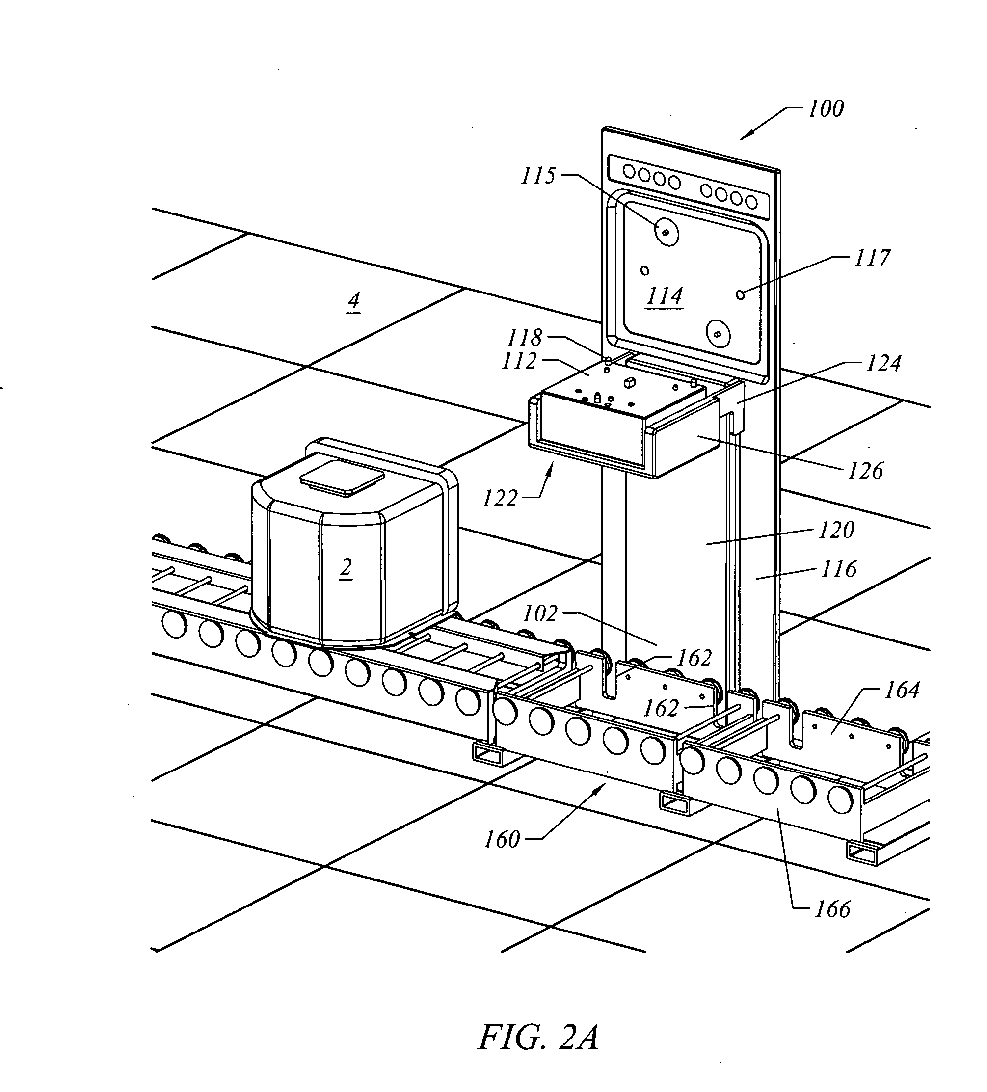
[0041] Semiconductor Equipment and Materials International (SEMI) has created standards for semiconductor wafer manufacturing equipment (see http: / / www.semi.org). The SEMI Standards govern acceptable tolerances and interfaces for semiconductor manufacturing equipment. The inventions described herein are not limited to semiconductor manufacturing equipment for handling FOUPs.

[0042] By way of example only, the various embodiments of the present invention may also be used and / or adapted for systems handling SMIF pods, reticle containers, flat panel display transport devices, or any other container or processing tool. Container is defined as any type of structure for supporting an article including, but not limited to, a semiconductor substrate. By way of example only, a container comprises a structure that comprises an open volume whereby the article can be accessed (e.g., FPD transport) or a container having a mechanically openable door (e.g., SMIF pod and FOUP). Load port is defined...


PUM


Abstract

The present invention comprises a container transport and loading system. The system generally comprises a load port for presenting articles to a tool and a container transport system. In one embodiment, the load port includes a vertically movable FOUP advance plate assembly that is adapted to load and unload a FOUP from a conveyor that passes by the load port and move the FOUP horizontally. In another embodiment, the load port includes a vertically movable support structure that is adapted to load and unload a container from a shuttle that passes by the load port. The various embodiments of the load port and container transport system are improvements over conventional container transport systems. The present invention also includes a shuttle for simultaneously transporting multiple containers that a load port may load or unload a container from.

Description

FIELD OF THE INVENTION [0001] The present invention generally relates to an automated material handling system (AMHS). More specifically, the present invention comprises a load port having a vertically movable container support structure that is able to load and unload containers directly from a container transport system. BACKGROUND OF THE INVENTION [0002] It is costly to deliver containers, such as Front Opening Unified Pods (FOUPs) and Standard Mechanical Interface (SMIF) pods, to processing tools and load ports in a semiconductor fabrication facility. One method of delivering FOUPs between processing tools is an overhead transport (OHT) system. The OHT system lowers a FOUP onto the kinematic plate of the load port at approximately 900 mm height from the fabrication facility floor. An OHT system uses sophisticated ceiling mounted tracks and cable hoist vehicles to deliver FOUPs to, for example, a load port of a processing tool. The combination of horizontal moves, cable hoist ext...

Claims


Application Information

Patent Timeline
Patent Type & Authority Applications(United States)
IPC IPC(8): H01L21/677
CPCH01L21/67775H01L21/67736Y10S414/14H01L21/00
Inventor BONORA, ANTHONY C.KROLAK, MICHAELHINE, ROGER G.
Owner MURATA MASCH LTD
Why Eureka
Try Eureka