Mounting structure for sprinklers
a technology for mounting structures and sprinklers, which is applied in the direction of filing appliances, machine supports, and suspension devices of curtain suspension devices, etc., can solve the problem of inefficiency of the conventional sprinkler mounting process
- Summary
- Abstract
- Description
- Claims
- Application Information
AI Technical Summary
Benefits of technology
Problems solved by technology
Method used
Image
Examples
first embodiment
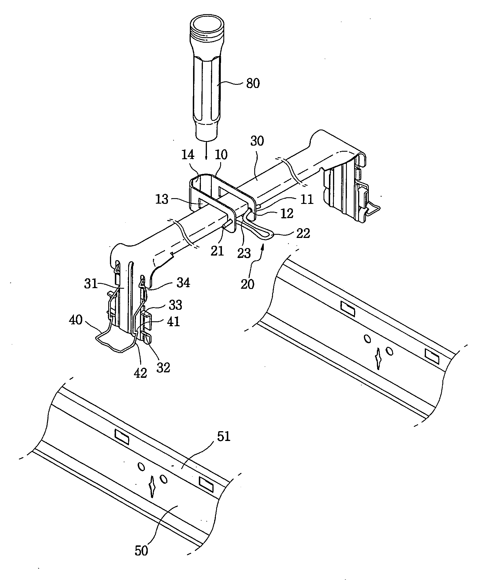
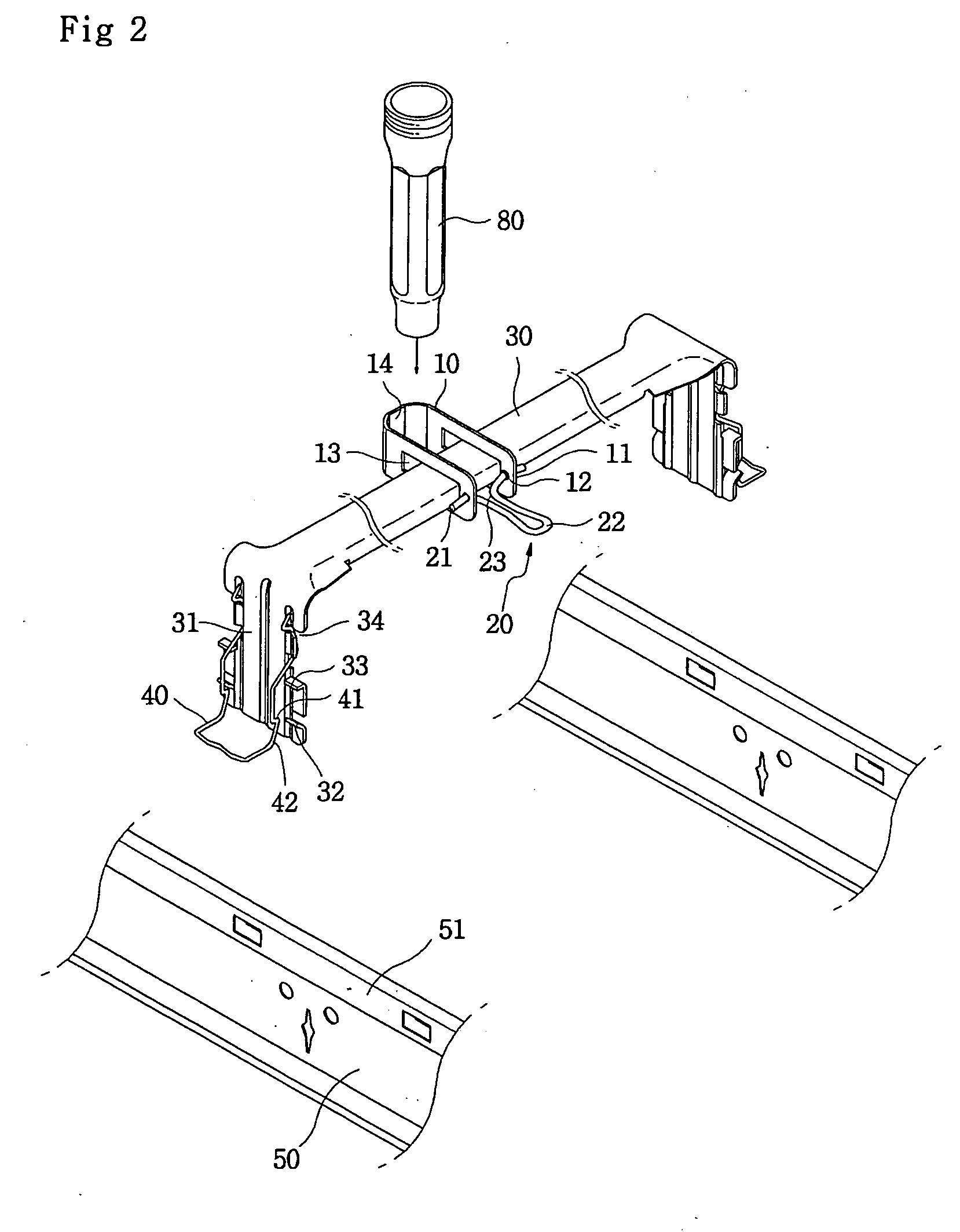
[0042]FIGS. 13A through 13C are views showing holding parts 14 of mounting brackets 10 to more reliably couple the sprinkler reducer to the latitudinal support unit 30, according to modifications of the present invention. FIG. 13A shows a knurled portion provided in a holding part 14 of a mounting bracket 10. FIG. 13B shows a vertically elongated protrusion 14a provided in a holding part 14 of a mounting bracket 10. In the case of FIG. 13B, the sprinkler reducer 80 has a vertically elongated groove at a predetermined position to correspond to the vertically elongated protrusion 14a of the holding part 14. FIG. 13C shows a horizontally elongated protrusion 14b provided in a holding part 14 of a mounting bracket 10. In the case of FIG. 13C, the sprinkler reducer 80 has a horizontally elongated groove at a predetermined position to correspond to the horizontally elongated protrusion 14b of the holding part 14.
[0043] In the present invention having the above-mentioned structure, to coup...
second embodiment
[0049] In the case of the second embodiment, the sprinkler reducer 80, which is coupled at an end thereof to a fire water pipe 90, is vertically placed at a predetermined position to be-in contact with a side of the latitudinal support unit 30.
[0050] In this state, to mount the mounting bracket 10A to the latitudinal support unit 30A, the latitudinal support unit 30A is horizontally inserted into the mounting space 13A of the mounting bracket 10A through the mouth 13C. At this time, the first end of the bracket arms, defining the mouth 13C and the mounting space 13A, is positioned outside the sprinkler reducer 80 (see, FIG. 8A).
[0051] Thereafter, the mounting bracket 10A, fitted over the latitudinal support unit 30, is rotated around the support part 13B so that the bracket arms surround the sprinkler reducer 80 and the other side of the sprinkler reducer 80 passes through the mouth 13C. Then, a holding part 14A of the mounting bracket 10A comes into close contact with an outer sur...
PUM
 Abstract
Description
Claims
Application Information
 - R&D
- Intellectual Property
- Life Sciences
- Materials
- Tech Scout
- Unparalleled Data Quality
- Higher Quality Content
- 60% Fewer Hallucinations
Browse by: Latest US Patents, China's latest patents, Technical Efficacy Thesaurus, Application Domain, Technology Topic, Popular Technical Reports.
© 2025 PatSnap. All rights reserved.Legal|Privacy policy|Modern Slavery Act Transparency Statement|Sitemap|About US| Contact US: help@patsnap.com


