Light-emitting diode device and method of manufacturing thereof

a technology of light-emitting diodes and diodes, which is applied in the direction of instruments, lighting and heating apparatus, non-linear optics, etc., can solve the problems of difficult to provide a relatively large amount of fluorescent materials in the region, and difficult to obtain favorable color mixtures, etc., to achieve favorable color mixtures, small variation in chromaticity of color-mixed light, and the effect of avoiding deterioration

Inactive Publication Date: 2006-08-31
SHARP KK
View PDF11 Cites 79 Cited by
  • Summary
  • Abstract
  • Description
  • Claims
  • Application Information

AI Technical Summary

Benefits of technology

[0020] In accordance with the present invention, the LED device can be provided without deterioration in light extraction efficiency, having favorable color mixture and small variation in chromaticity of the color-mixed light. Further, since such agents as light-scattering agent and anti-settling agent are not used, the product cost is low and the production line can be simplified. Furthermore, the LED device is easy applicable to small-volume manufacturing of a wide variety of products.

Problems solved by technology

In the case where an LED chip having the radiation characteristics as shown in FIG. 9C is used, however, the following problem arises.
Actually, however, it is difficult to provide a relatively large amount of the fluorescent material in the region near the top surface of the chip where the amount of light is large and provide a relatively small amount of the fluorescent material in the region near the bottom surface of the package where the amount of light is small.
Thus, in this case, it is difficult to obtain a favorable color mixture.
The light-scattering agent, however, absorbs a considerable amount of light while reflecting light.
However, even in the process of injecting the resin, the fluorescent material is settling in the container used for the injection.
Therefore, it is difficult to inject a uniform amount of the fluorescent material into the package.
Thus, the fluorescent material is settling in the injection container in the injection process, leading to difficulty in injection into the package at an even concentration.
Thus, it is difficult to keep constant the concentration of the fluorescent material injected into the package and it is also difficult to uniformly arrange and distribute the fluorescent material within the package.
Therefore, it is likely that the chromaticity of the color-mixed light is uneven.
However, since the anti-settling agent is also comprised of superfine particles like silica (SiO2), absorption of light as well as resultant deterioration in light extraction efficiency of the LED device occur, as occurs in the case where the aforementioned light-scattering agent is used.

Method used


Image

  • Light-emitting diode device and method of manufacturing thereof
  • Light-emitting diode device and method of manufacturing thereof
  • Light-emitting diode device and method of manufacturing thereof

Examples


Embodiment Construction
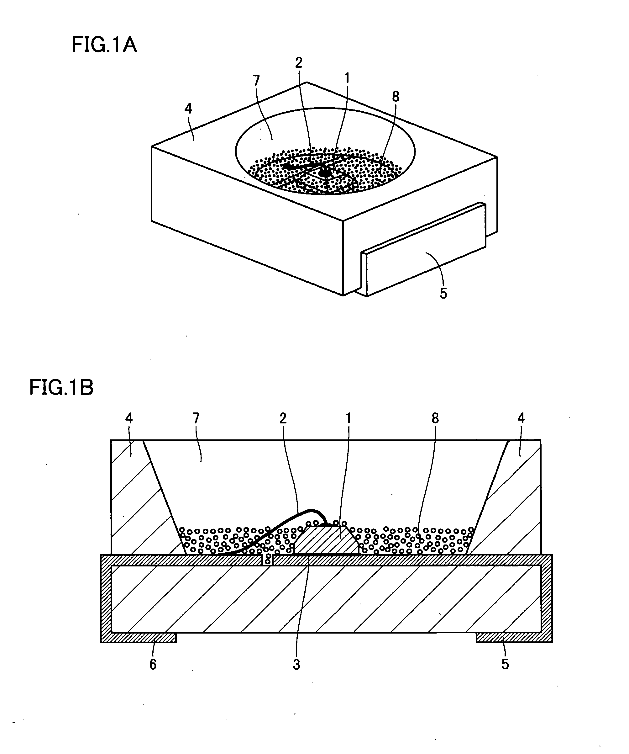
[0033] LED Device

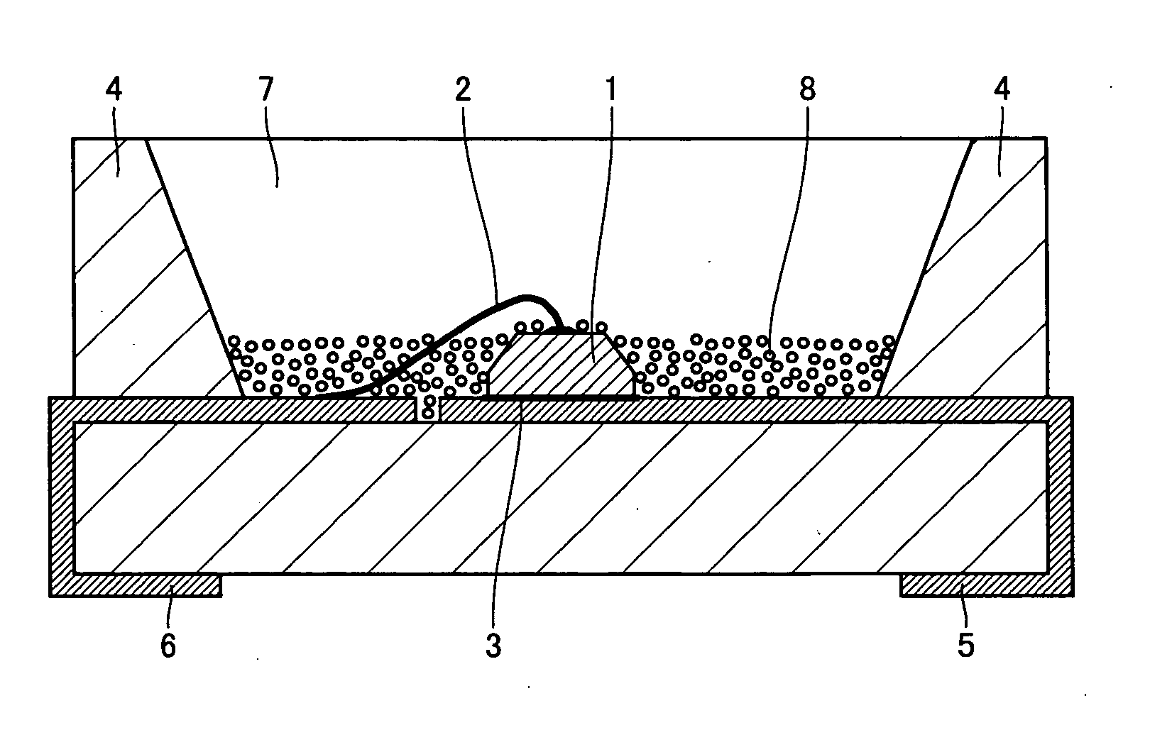
[0034]FIG. 1A is a perspective view of a surface-mounted light-emitting diode device as a typical example of the LED device of the present invention. FIG. 1B is a cross-sectional view of the LED device. The device includes a pair of positive and negative electrodes 5, 6 formed of a metal plate and a package 4 made of a heat-resistant resin. Package 4 can be formed by the insert molding and is in the shape of a reflection cup. An LED chip 1 has a side-surface portion and a top-surface portion and a part of the side-surface portion is an inclined surface. LED chip 1 is electrically connected within package 4 to one electrode 5 through an electrically conductive material 3 and to the other electrode 6 by a metal wire 2.

[0035] Package 4 is sealed with a translucent resin 7 and, near its bottom surface, a fluorescent material 8 is provided in a layer form with a substantially uniform thickness. The layer of fluorescent material 8 is formed to cover a part or the whole ...


PUM


Abstract

An LED device that is excellent in color mixture and small in variation of chromaticity is provided. The LED device includes, in a package, an LED chip, a fluorescent material excited by light from the LED chip to generate light with a wavelength different from that of the light from the LED chip, and a translucent resin holding the fluorescent material. The LED chip has a side-surface portion, a top-surface portion, a bottom-surface portion, and a light-emitting layer sandwiched between the top-surface portion and the bottom-surface portion, and the fluorescent material in the translucent resin is provided in a layer form on a bottom surface of the package to entirely or partially cover the side-surface portion of the LED chip.

Description

[0001] This nonprovisional application is based on Japanese Patent Application No. 2005-054141 filed with the Japan Patent Office on Feb. 28, 2005, the entire contents of which are hereby incorporated by reference. BACKGROUND OF THE INVENTION [0002] 1. Field of the Invention [0003] The present invention relates to a light-emitting diode device used in such applications as backlight of a liquid-crystal display, a panel meter and an indicator light. In particular, the invention relates to white and intermediate-color light-emitting diode devices and a method of manufacturing thereof. [0004] 2. Description of the Background Art [0005] A conventional light-emitting diode (hereinafter also referred to as “LED”) has a device structure as shown in FIGS. 10A and 10B. As shown in FIGS. 10A and 10B, the LED device includes, within its package 14, an LED chip 11, a fluorescent material 18 excited by light from LED chip 11 to generate light with a different wavelength, and a translucent resin 1...

Claims


Application Information

Patent Timeline
Patent Type & Authority Applications(United States)
IPC IPC(8): F21V9/16H01L33/50H01L33/60H01L33/32
CPCG02F1/133603H01L33/20H01L33/508H01L2933/0041H01L2224/48091H01L2224/48247H01L2224/48257H01L2224/48465H01L2224/73265H01L2224/8592H01L2924/10157H01L2924/10155H01L2924/00014H01L2924/00
Inventor KAMOSHITA, SHOHICHI
Owner SHARP KK
Why Eureka
Try Eureka