
Object detection apparatus, learning apparatus, object detection system, object detection method and object detection program

Inactive Publication Date: 2006-08-31
KK TOSHIBA
View PDF12 Cites 21 Cited by
  • Summary
  • Abstract
  • Description
  • Claims
  • Application Information

AI Technical Summary

Benefits of technology

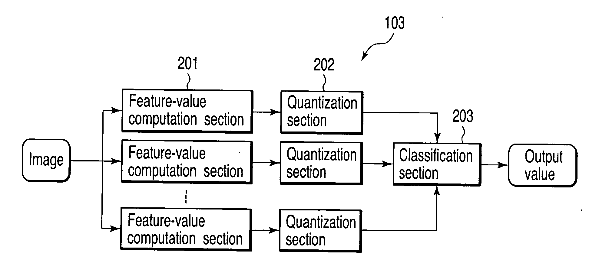
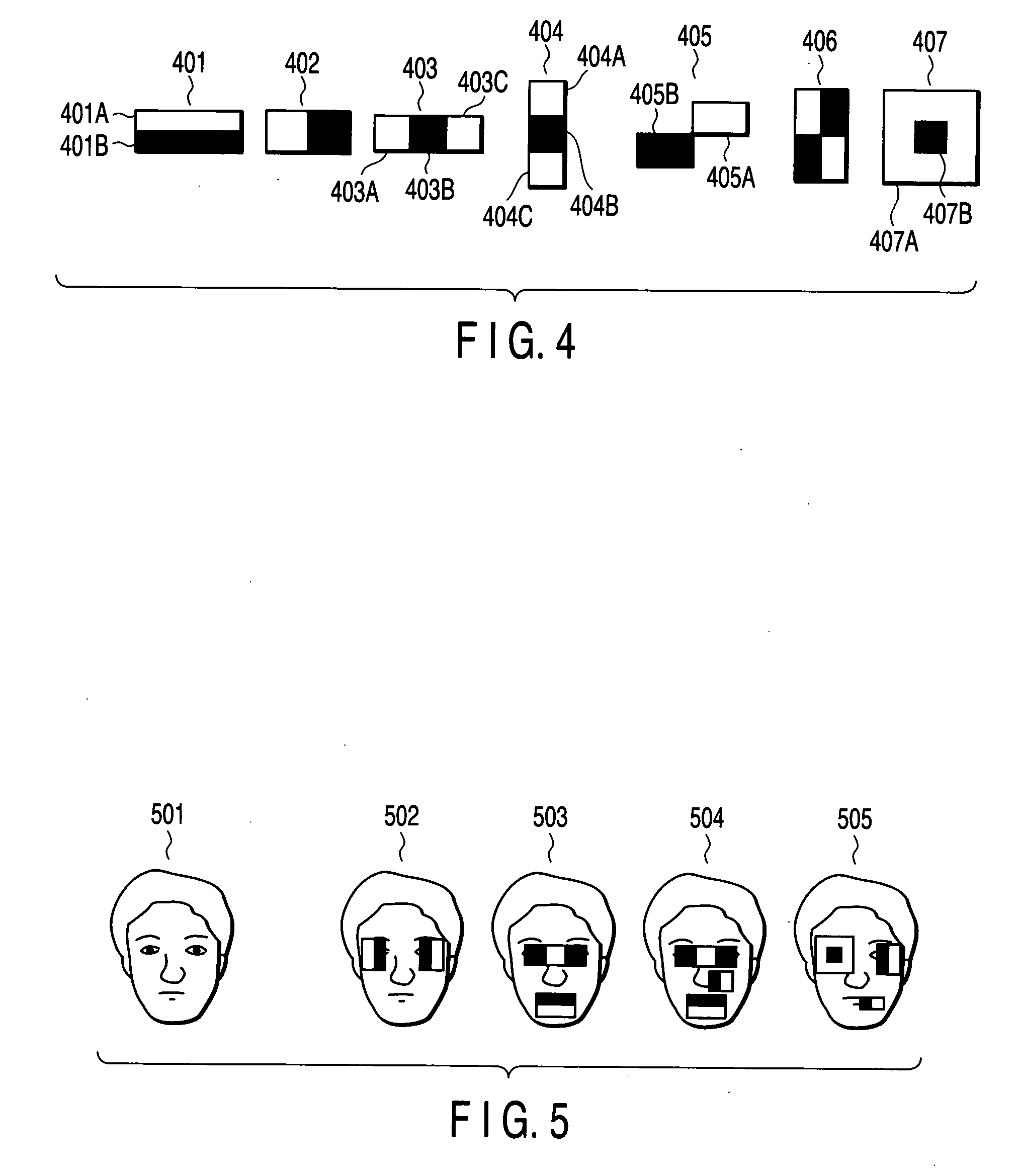
[0008] In accordance with a second aspect of the invention, there is provided a learning apparatus comprising: a first storing unit configured to store at least two sample images, one of the sample images being an object as a detection target and the other sample image being a non-object as a non-detection target; a feature generation unit configured to generate a plurality of feature areas each of which includes a plurality of pixel areas, the feature areas being not more than a maximum number of feature areas which are arranged in each of the sample images; a feature computation unit configured to compute, for each of the sample images, a feature value of each of the feature areas; a probability computation unit configured to compute a probability of occurrence of the feature value corresponding to each of the feature areas, depending upon whether each of the sample images is the object, and then to quantize the feature value into one of a plurality of discrete values based on the computed probability; a combination generation unit configured to generate a plurality of combinations of the feature areas; a joint probability computation unit configured to compute, in accordance with each of the combinations, a joint probability with which the quantized feature quantities are simultaneously observed in each of the sample images, and generate tables storing the generated combinations, the computed joint probabilities, and information indicating whether each of the sample images is the object or the non-object; a determination unit configured to determine, concerning each of the combinations with reference to the tables, whether a ratio of a joint probability indicating the object sample image to a joint probability indicating the non-object sample image is higher than a threshold value, to determine whether each of the sample images is the object; a selector configured to select, from the combinations, a combination which minimizes number of errors in determination results corresponding to the sample images; and a second storing unit which stores the selected combination and one of the tables corresponding to the selected combination.
[0024] wherein: the acquisition means instructs the computer to generate tables storing the generated combinations, a plurality of values obtained by multiplying the computed joint probabilities by the updated weight, and information indicating whether each of the sample images is the object or the non-object; the determination means instructs the computer to perform a determination based on the values obtained by multiplying the computed joint probabilities by the updated weight; the selection means instructs the computer to select, from a plurality of combinations determined based on the updated weight, a combination which minimizes number of errors in determination results corresponding to the sample images; and the storing means instructs the computer to newly store the selected combination, and one of the tables corresponding to the selected combination.

Problems solved by technology

Using such a single feature value, the correlation between features contained in an object, for example, symmetry of features of the object, cannot effectively be estimated, resulting in a low recognition accuracy.
It is apparent that combination of such low-accuracy classifiers will not greatly enhance the recognition accuracy.

Method used


Image

  • Object detection apparatus, learning apparatus, object detection system, object detection method and object detection program
  • Object detection apparatus, learning apparatus, object detection system, object detection method and object detection program
  • Object detection apparatus, learning apparatus, object detection system, object detection method and object detection program

Examples


Embodiment Construction

[0039] Referring to the accompanying drawings, a detailed description will be given of an object detection apparatus, learning apparatus, object detection system, object detection method and object detection program according to an embodiment of the invention.

[0040] The embodiment has been developed in light of the above, and aims to provide an object detection apparatus, learning apparatus, object detection system, object detection method and object detection program, which can detect and enable detection of an object with a higher accuracy than in the prior art.

[0041] The object detection apparatus, learning apparatus, object detection system, object detection method and object detection program of the embodiment can detect an object and enable detection of an object with a higher accuracy than in the prior art.

[0042] (Object Detection Apparatus)

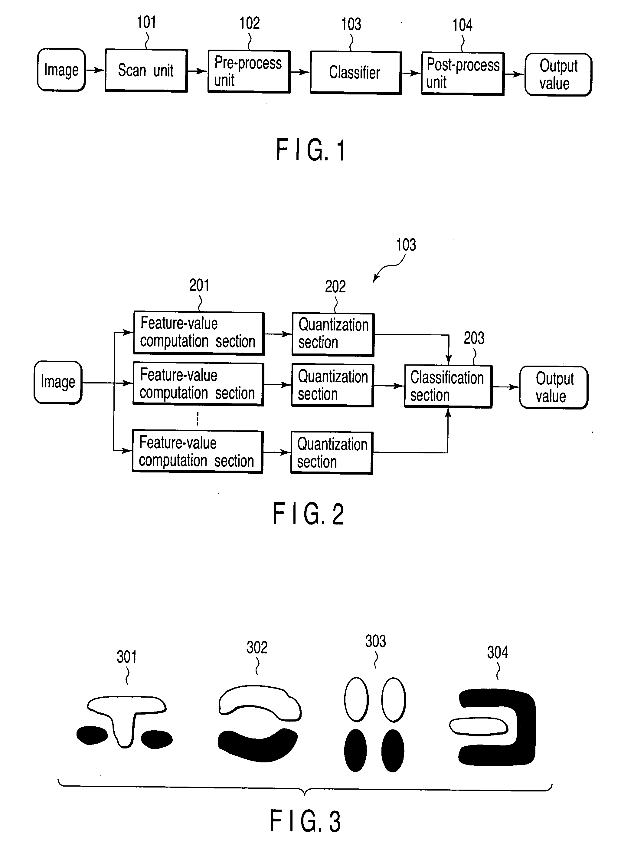
[0043] Referring first to FIG. 1, the object detection apparatus of the embodiment will be described.

[0044] As shown, the object det...


PUM


Abstract

Object detection apparatus includes storing unit storing learned information learned previously with respect to sample image extracted from an input image and including first information and second information, first information indicating at least one combination of given number of feature-region / feature-value groups selected from plurality of feature-region / feature-value groups each including one of feature areas and one of quantized learned-feature quantities, feature areas each having plurality of pixel areas, and quantized learned-feature quantities obtained by quantizing learned-feature quantities corresponding to feature quantities of feature areas in sample image, and second information indicating whether sample image is an object or non-object, feature-value computation unit computing an input feature value of each of feature areas belonging to combination in input image, quantization unit quantizing computed input feature value to obtain quantized input feature value, and determination unit determining whether input image includes object, using quantized input feature value and learned information.

Description

CROSS-REFERENCE TO RELATED APPLICATIONS [0001] This application is based upon and claims the benefit of priority from prior Japanese Patent Application No. 2005-054780, filed Feb. 28, 2005, the entire contents of which are incorporated herein by reference. BACKGROUND OF THE INVENTION [0002] 1. Field of the Invention [0003] The present invention relates to an object detection apparatus, learning apparatus, object detection system, object detection method and object detection program. [0004] 2. Description of the Related Art [0005] There is a method of using the brightness difference value between two pixel areas as a feature value for detecting a particular object in an image (see, for example, Paul Viola and Michael Jones, “Rapid Object Detection using a Boosted Cascade of Simple Features”, IEEE conf. on Computer Vision and Pattern Recognition (CVPR), 2001). The feature value can be calculated efficiently if the pixel area is rectangular, and is therefore widely utilized. The method...

Claims


Application Information

Patent Timeline
IPC IPC(8): G06K9/46G06K9/62
CPCG06K9/00248G06V40/165
Inventor MITA, TAKESHIKANEKO, TOSHIMITSUHORI, OSAMU
Owner KK TOSHIBA
Learn More