Ultra-precision machine tool

a technology of ultra-precision machine tools and workpieces, applied in the direction of manufacturing tools, metal-working machine components, planing/slotting apparatuses, etc., can solve the problems of machining errors, movement errors between tools and workpieces, and accumulation of elastic deformation in each portion, so as to achieve the effect of minimizing errors

Inactive Publication Date: 2010-03-04
DMG MORI SEIKI CO LTD
View PDF8 Cites 14 Cited by
  • Summary
  • Abstract
  • Description
  • Claims
  • Application Information

AI Technical Summary

Benefits of technology

[0006]An object of this invention is to provide a 5-axis motion control ultra-precision machine tool in which major portions are composed as a structure completely symmetric about the machining point so as to minimize errors due to thermal displacement.

Problems solved by technology

However, the table or the machining head is disposed in an asymmetric manner about the machining point in the machine tool described in said U.S. Pat. No., so that there is a fear that machining errors appear due to thermal displacement of the table or the machining head.
Further, the length of the force loop between the tool and the workpiece is long because the machining head is supported on the column with an overhang, thus elastic deformation is accumulated in each portion and there appears errors of movement between the tool and the workpiece.

Method used


Image

  • Ultra-precision machine tool
  • Ultra-precision machine tool
  • Ultra-precision machine tool

Examples


Embodiment Construction

[0037]Explanation will be made about preferred embodiments of this invention referring with accompanied drawings.

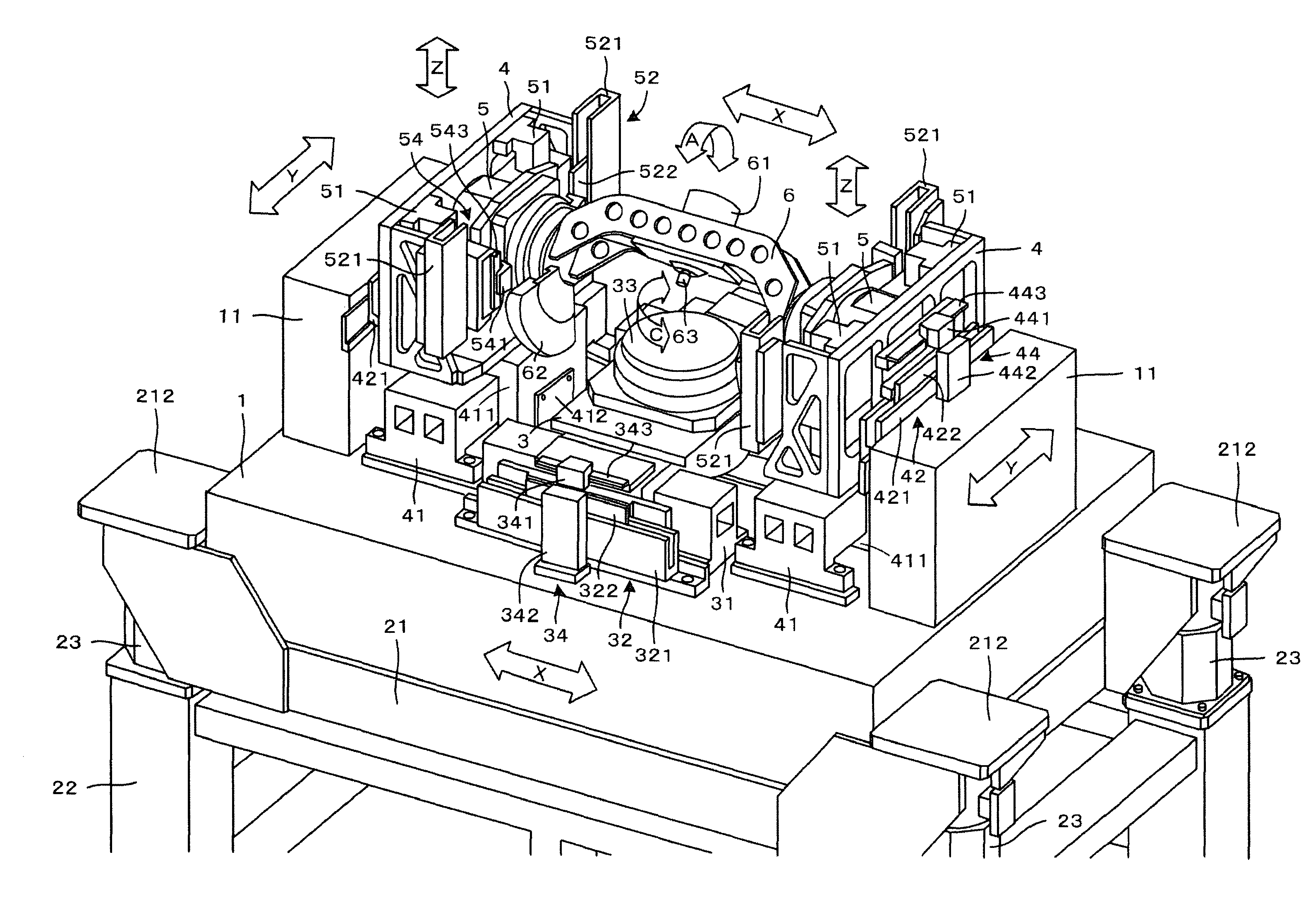
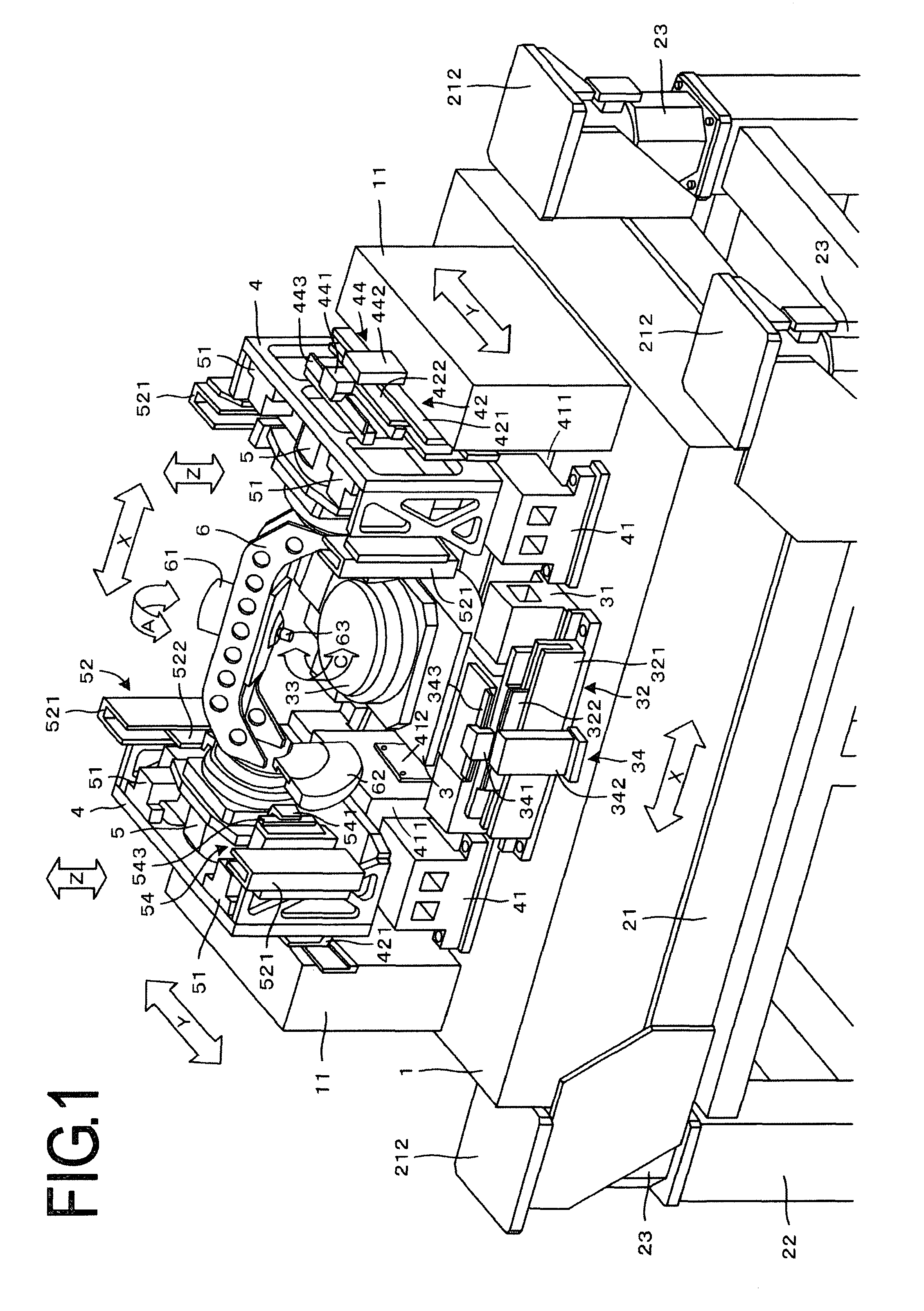
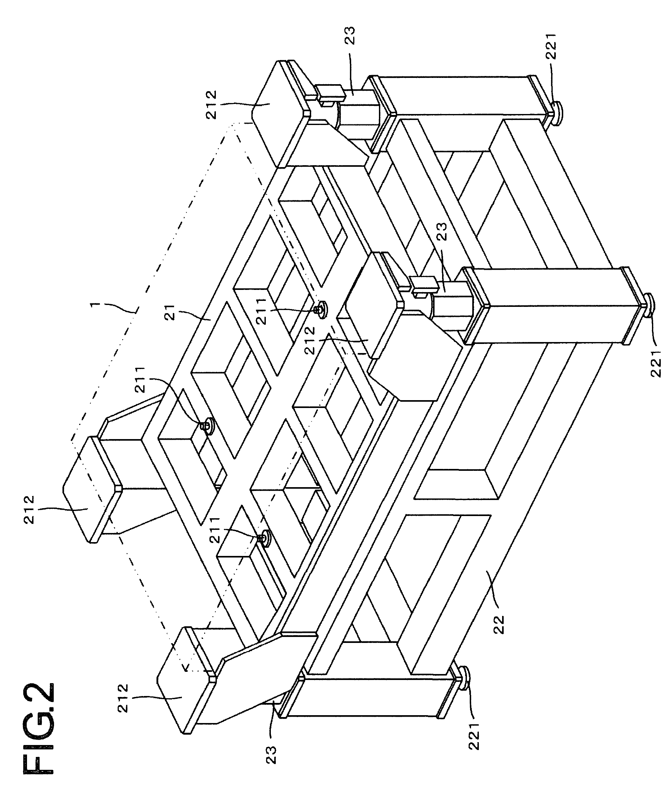
[0038]The material of the rectangular base 1 supporting the ultra-precision machine tool arranged according to this invention, shown in FIGS. 1 and 2, is granite which has a low thermal expansion coefficient. As shown in detail in FIG. 2, the base 1 is placed on the upper frame 21 disposed on the lower frame 22 which is placed on the floor. The upper and lower frames 21 and 22 are formed by welding tube members (hollow pipes) with rectangular cross-sections. Four leveling devices 221 are disposed beneath the bottom face of the lower frame 22 at the four corners, thereby supporting the lower frame 22 on the floor at four positions. The leveling devices 221 are to adjust the altitude of the lower frame 22 and each of the leveling devices 221 is composed of a leveling seat and a leveling bolt.

[0039]Supporting rubber pads 211 are disposed at three positions between the upper ...


PUM

PropertyMeasurementUnit
center of massaaaaaaaaaa
massaaaaaaaaaa
surface roughnessaaaaaaaaaa

Abstract

A 5 axis motion controlled ultra-precision machine tool is provided in which major portions are composed as a structure completely symmetric about the machining point and errors due to thermal displacement can be minimized.
A pair of Y axis guide members (41,41) are secured to the top face of a base (1) at both sides of an X axis slider (3) interposed therebetween for X direction so as to movably guide Y axis sliders (4,4) in horizontal Y direction perpendicular to X axis. Y axis linear motors (42,42) and the Y axis guide members (41,41) are disposed substantially at the center of mass of the Y axis sliders (4,4) respectively, so that the Y axis sliders (4,4) can be driven in Y direction with vibration and errors in alignment minimized.

Description

FIELD OF THE INVENTION[0001]This invention relates to an ultra-precision machine tool, specifically to a 5-axis motion control ultra-precision machine tool. More specifically, this invention relates to an ultra-precision machine tool for machining a workpiece which is made up of a structure of micrometer level or composed so as to have curved faces of micrometer level with a surface roughness of nanometer level.BACKGROUND ART[0002]Precision parts or devices, such as light guiding panels, micro-needle arrays, micro-fluid channels, micro prism retroreflectors, lens arrays, etc., are used in the fields of optics, biotechnology, electronics, mechatronics and so on.[0003]These precision parts are composed of structures of micrometer level or composed so as to have curved faces of micrometer level, which are required to have a surface roughness of nanometer level. Most of these parts are fabricated by molding of plastics or glass, so that dies for mass production of these parts are needed...

Claims


Application Information

Patent Timeline
Patent Type & Authority Applications(United States)
IPC IPC(8): B23B7/00
CPCB23Q1/015B23Q1/623Y10T82/2502Y10T29/5114Y10T409/309576Y10T409/307672Y10T82/2531Y10T82/2543Y10T409/305656Y10T409/304312Y10T409/309688
Inventor KIM, CHANG-JUPADDEN, TERENCEKIM, JONGSOO
Owner DMG MORI SEIKI CO LTD
Why Eureka
Try Eureka