Facilitating electronic payment on behalf of a customer of electronic presented bills

a technology of electronic payment and bill, applied in the field of distributed data accessing technique, can solve the problem that neither of the above-described models adopts a truly customer-centric view

Inactive Publication Date: 2006-08-31
CHECKFREE CORP
View PDF79 Cites 12 Cited by
  • Summary
  • Abstract
  • Description
  • Claims
  • Application Information

AI Technical Summary

Benefits of technology

[0009] One object of the present invention is to provide a distributed data accessing technique that allows a customer to interact directly with individual billers while retaining the benefits of interacting with a single aggregator.
[0010] Another object of the present invention is to provide a distributed data accessing technique that allows a customer to retain the benefits of interacting with a single aggregator while allowing the aggregator, billers, and sponsor to retain control of customer-related data and a communication channel with each customer.
[0011] Another object of the present invention is to provide a distributed data accessing technique that allows complete flexibility as to who is offering bill presentment: billers only, aggregator only (possibly on behalf of one or more sponsors), or some combination of the above.
[0012] Another object of the present invention is to provide a distributed data accessing technique that supports an end-to-end audit trail from the initial stages of bill presentment to the final stages of bill payment, which can serve a variety of purposes, including improved customer care.

Problems solved by technology

Also, neither of the above-described models adopt a truly customer-centric view.

Method used


Image

  • Facilitating electronic payment on behalf of a customer of electronic presented bills
  • Facilitating electronic payment on behalf of a customer of electronic presented bills
  • Facilitating electronic payment on behalf of a customer of electronic presented bills

Examples


Embodiment Construction

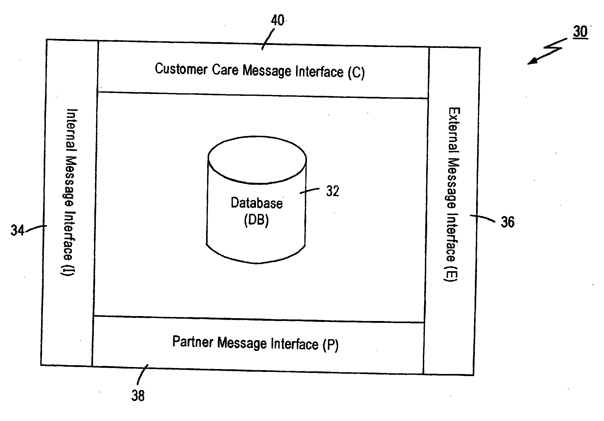
[0049] Referring to FIG. 3, there is shown an infrastructure diagram of a distributed database entity 30 in accordance with the present invention. The distributed database entity 30 comprises a database component 32 and a plurality of message interfaces 34-40 for facilitating communication between the database component 32 and other distributed database entities and system components. The database component 32 typically contains data that is controlled or “owned” by the controller or “owner” of the distributed database entity 30. For example, if the distributed database entity 30 is owned by a financial institution (FI) such as a bank, then the database component 32 could contain information such as checking and savings account balances. It should be noted, however, that the database component 32 can also contain data from other distributed database entities and system components, as will be described in detail below.

[0050] The plurality of message interfaces 34-40 includes an inte...


PUM


Abstract

To facilitate electronic presentment of a bill of a biller for a customer and payment of the presented bill on behalf of the customer via a communications network, a first network site associated with a bill payment entity receives a request for billing information from a second network site associated with a customer via a first communications link over a communications network. In response, a bill availability indicator indicative of an availability of a bill of the biller for the customer and having a first linking function, is presented to the second network site via the first communications link. The presented bill availability indicator is selectable at the second network site to activate the first linking function and thereby establish a second communications link over the communications network to a third network site associated with a bill presentment entity for presentment by the third network site to the second network site of a bill of the biller and an associated pay bill indicator having a second linking function to the first network site. The presented pay bill indicator is selectable at the second network site to activate the second linking function and thereby establish a third communications link over the communications network to the first network site for requesting payment of the presented bill of the biller.

Description

RELATED APPLICATIONS [0001] This application is a continuation of pending U.S. application Ser. No. ______ (Attorney Docket 3350-019B-CNT3), filed Feb. 15, 2005, which is a continuation of U.S. application Ser. No. 09 / 301,068, filed Apr. 28, 1999 (now U.S. Pat. No. 6,856,974), which is a continuation of U.S. application Ser. No. 09 / 017,169, filed Feb. 2, 1998 (now U.S. Pat. No. 6,055,567), the disclosures of which are incorporated herein by reference in their entirety. This application is also related to U.S. application Ser. No. 10 / 645,521 (Attorney Docket 3350-19B-CNT), filed Aug. 22, 2003; U.S. application Ser. No. ______ (Attorney Docket 3350-19B-CNT1), filed Feb. 17, 2005; U.S. application Ser. No. ______ (Attorney Docket 3350-19B-CNT4), filed concurrently herewith; and U.S. application Ser. No. ______, (Attorney Docket 3350-19B-CNT5), filed concurrently herewith.FIELD OF THE INVENTION [0002] The present invention relates generally to distributed data networks and, more particu...

Claims


Application Information

Patent Timeline
Patent Type & Authority Applications(United States)
IPC IPC(8): G06Q40/00
CPCG06Q20/102G06Q30/04
Inventor GANESAN, RAVIHARRIS, MARK TODDDREYER, HANS DANIELWOLFE, KATHRYN RANDALL
Owner CHECKFREE CORP
Why Eureka
Try Eureka