Hand tool apparatus and method

a technology of hand tools and tools, applied in the field of hand tools, can solve the problems of inability to easily and quickly disengage gauge tools, inability to adjust tools completely absent or cumbersome and imprecise, and inability to use gauge tools

Inactive Publication Date: 2006-09-07
WALCHAK NORMAN J
View PDF27 Cites 5 Cited by
  • Summary
  • Abstract
  • Description
  • Claims
  • Application Information

AI Technical Summary

Benefits of technology

[0004] The present invention comprises a hand tool for the installation of elongated horizontally overlapping siding on a vertical framework, the siding having a top edge portion, a bottom edge portion, an interior face and an exterior face, the hand tool comprising: a stationary jaw; a movable jaw opposing the stationary jaw, the movable jaw having an interior jaw face and an exterior jaw face, the interior jaw face having a horizontal plate carried thereon, the exterior jaw face being substantially flat; a slide bar, having a first bar end and a second bar end with a portion therebetween, the movable jaw being carried on the first bar end, the slide bar being movable to bring the movable jaw toward and away from the stationary jaw; a housing, having an upper portion, a middle portion and a lower portion, the stationary jaw being carried on the upper portion of the housing, the middle portion having a channel formed therein for slidably receiving and supporting the slide bar, the lower portion having a handgrip; an adjustable arm carried on the upper portion of the housing adjacent the stationary jaw, for adjustably aligning an uninstalled siding piece about an installed siding piece; an adjustable stop member carried on one end of the adjustable arm, for supporting the uninstalled siding piece and preventing the uninstalled siding piece from sliding out of alignment with the installed siding piece; a single direction drive system having an advancement handle pivotably mounted to the housing in engageable contact with the drive system for releasably engaging the slide bar and when engaged, for advancing the slide bar and carried movable jaw toward the stationary jaw; and a retention system having a retention handle extending outwardly from the housing forwardly of the advancement handle for releasably disengaging, the retention slide bar normally engaging the slide bar, and when engaged preventing motion of the movable jaw away from the stationary jaw, and when disengaged, permitting motion of the movable jaw away from the stationary jaw, wherein the hand tool is grippable about the handgrip, the advancement handle and retention handle being selectively operable by the same hand, permitting a single person to manipulate long pieces of uninstalled vertical siding and properly position the long pieces of uninstalled siding relative to an installed piece of siding.
[0005] The present invention further comprises a method for manufacturing a hand tool for the installation of elongated horizontally overlapping siding on a vertical framework, the siding having a top edge portion, a bottom edge portion, an interior face and an exterior face, the hand tool comprising: providing a stationary jaw; providing a movable jaw opposing the stationary jaw, the movable jaw having an interior jaw face and an exterior jaw face, the interior jaw face having a horizontal plate carried thereon, the exterior jaw face being substantially flat; providing a slide bar, having a first bar end and a second bar end with a portion therebetween, the movable jaw being carried on the first bar end, the [slide] bar being movable to bring the movable jaw toward and away from the stationary jaw; providing a housing, having an upper portion, a middle portion and a lower portion, the stationary jaw being carried on the upper portion of the housing, the middle portion having a channel formed therein for slidably receiving and supporting the slide bar, the lower portion having a handgrip; providing an adjustable arm carried on the upper portion of the housing adjacent the stationary jaw, for adjustably aligning an uninstalled siding piece about an installed siding piece; providing an adjustable stop member carried on one end of the adjustable arm, for supporting the uninstalled siding piece and preventing the uninstalled siding piece from sliding out of alignment with the installed siding piece; a single direction drive system having an advancement handle pivotably mounted to the housing in engageable contact with the drive system for releasably engaging the slide bar and when engaged, for advancing the slide bar and carried movable jaw toward the stationary jaw; and providing a retention system having a retention handle extending outwardly from the housing forwardly of the advancement handle for releasably disengaging, the retention slide bar normally engaging the slide bar, and when engaged preventing motion of the movable jaw away from the stationary jaw, and when disengaged, permitting motion of the movable jaw away from the stationary jaw, wherein the hand tool is grippable about the handgrip, the advancement handle and retention handle being selectively operable by the same hand, permitting a single person to manipulate long pieces of uninstalled vertical siding and properly position the long pieces of uninstalled siding relative to an installed piece of siding.

Problems solved by technology

A disadvantage in these previous tools lies in the fact that none of the previous hand tools are capable of acting as a third-hand to assist the installation and proper spacing of elongated horizontally overlapping siding on a vertical framework.
The disadvantage of previous siding gauge tools, for example U.S. Pat. No. 6,684,521 by Rempe and U.S. Pat. No. 6,637,160 by Rempe, lies in the fact that adjustment of the tool either totally absent or cumbersome and imprecise.
Further, these gauge tools are not easily nor quickly disengaged, nor are they capable of being operated by a single hand.

Method used


Image

  • Hand tool apparatus and method
  • Hand tool apparatus and method
  • Hand tool apparatus and method

Examples


Embodiment Construction

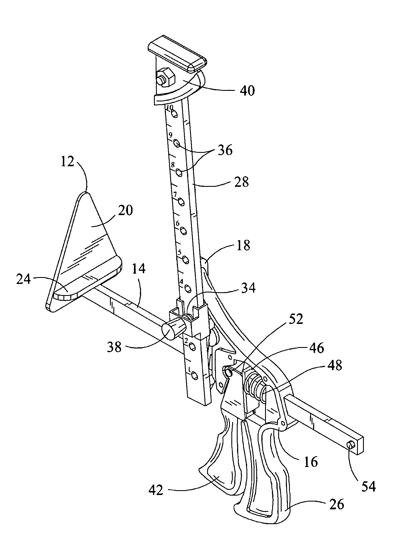
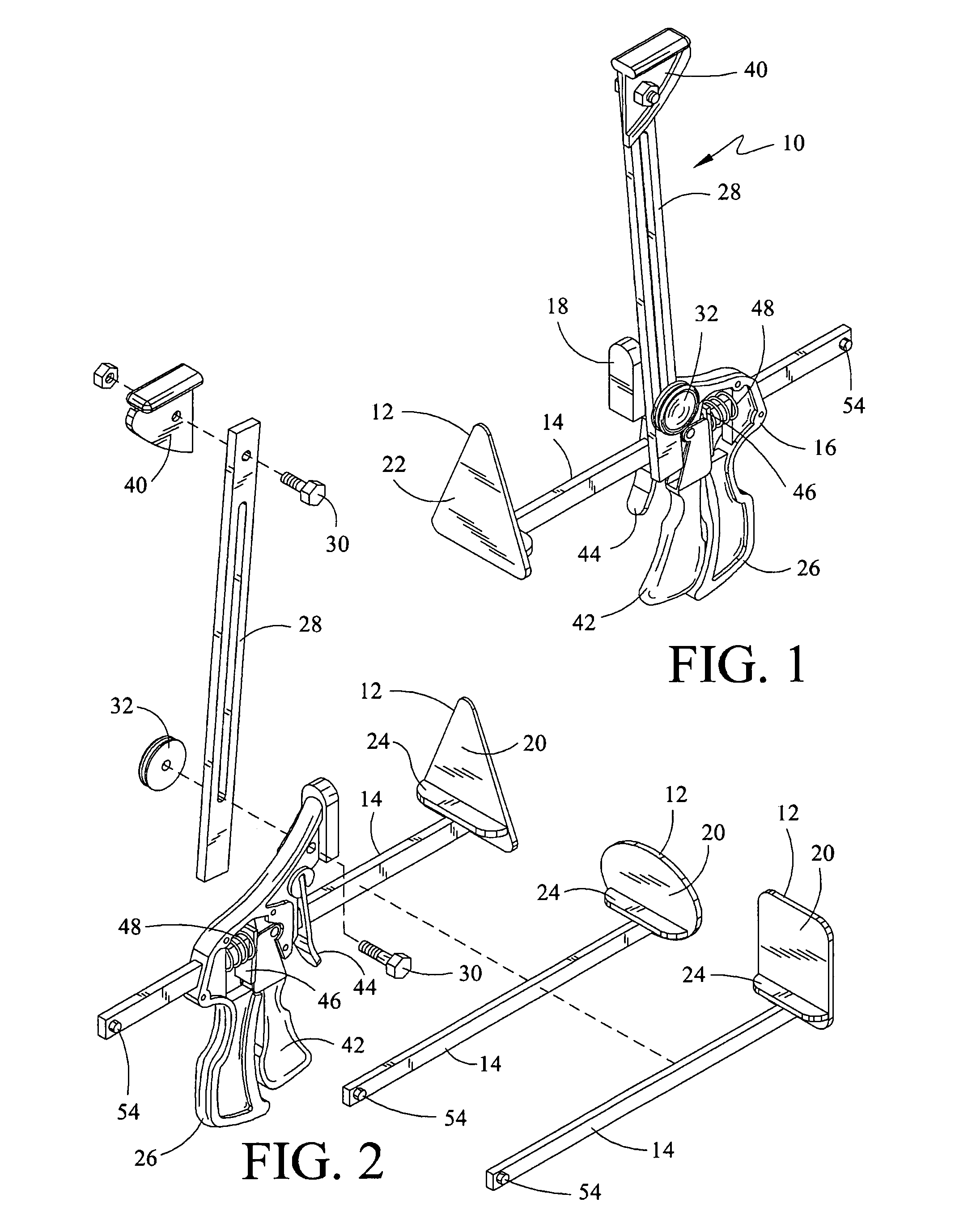
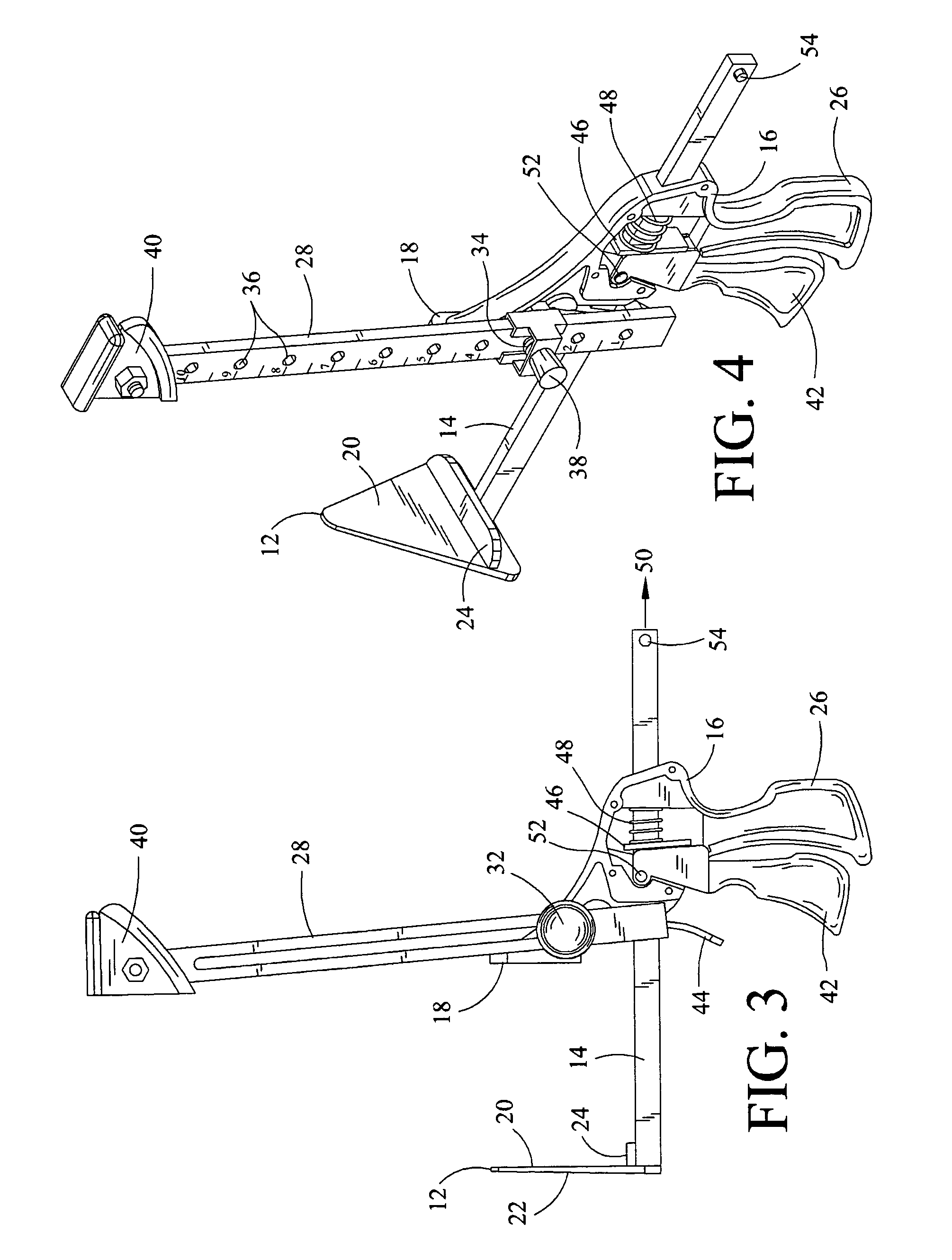
[0011] With reference to the Drawings wherein like number indicate like elements, a hand tool shown generally at 10, includes a movable jaw 12 connected to a slide bar 14. The slide bar is slidably supported in a channel that passes through a housing assembly 16.

[0012] The movable jaw 12 opposes the stationary jaw 18, and has an interior face 20 and an exterior face 22. The interior face 20 of the movable jaw 12 carries a horizontal plate 24 for receiving and supporting a bottom edge portion of a siding piece to be clamped.

[0013] Slide bar 14 has a first bar end and a second bar end, with a bar portion therebetween. The movable jaw 12 is carried on the first bar end, the slide bar being movable to bring the movable jaw toward and away from the stationary jaw.

[0014] The housing assembly 16 includes an upper portion, a middle portion, and a lower portion. The stationary jaw 18 is carried on the upper portion of the housing assembly 16 opposing the moveable jaw 12. A channel is carr...


PUM


Abstract

The present invention comprises a hand tool for the installation of elongated horizontally overlapping siding on a vertical framework.

Description

BACKGROUND OF THE INVENTION [0001] This invention relates generally to a hand tool of the type used to temporarily clamp together two articles, for example, for gluing, or to hold a workpiece for nailing or welding, and more particularly to a hand tool for the installation and proper spacing of elongated horizontally overlapping siding on a vertical framework having a quick-action bar clamp wherein the moving jaw can be rapidly advanced or advances in small increments of selectable length. The concept of a bar clamp is old and well-known. In recent years, quick-action handgrips have been incorporated for use in final tightening against the workpiece, for example, in U.S. Pat. No. 6,648,315 by Lee, U.S. Pat. No. 5,022,137 by Sorensen, U.S. Pat. No. 4,926,722 by Sorensen, U.S. Pat. No. 4,088,313 by Pearson, and U.S. Pat. No. 4,563,921 by Wallace. A disadvantage in these previous tools lies in the fact that none of the previous hand tools are capable of acting as a third-hand to assist...

Claims


Application Information

Patent Timeline
Patent Type & Authority Applications(United States)
IPC IPC(8): G01D21/00
CPCB25B5/068B25B5/163Y10S269/904
Inventor WALCHAK, NORMAN J.
Owner WALCHAK NORMAN J
Why Eureka
Try Eureka