Aircraft fluid cooling system and aircraft provided with said system

Inactive Publication Date: 2006-09-07
AIRBUS
View PDF11 Cites 28 Cited by
  • Summary
  • Abstract
  • Description
  • Claims
  • Application Information

AI Technical Summary

Benefits of technology

[0014] Advantageously, the aircraft fluid cooling system that is the subject of this invention has at least one fan for ensuring a minimum throughput of air in the air heat exchanger. This fan allows for ensuring and improving the cooling of said fluid by increasing the throughput of air through the air heat exchanger,

Problems solved by technology

Generally, it is estimated that approximately 10% to 15% of the total power available to the pumps is lost as a result of the existence of these internal leaks, and that this power fraction is turned into heat.
Such heating of the hydraulic fluid has a harmful effect on the functioning of the hydraulic circuit.
In fact, this heating results in the degradation of the hydraulic fluid, and thus in a reduction in its performance.
In particular, heating of the fluid may lead to an increase in the acidity of said fluid, which can cause deterioration of the consumer mechanisms of said hydraulic fluid.
This heating may also lead to a deterioration of the joints in the hydraulic circuit, and consequently, e

Method used


Image

  • Aircraft fluid cooling system and aircraft provided with said system
  • Aircraft fluid cooling system and aircraft provided with said system
  • Aircraft fluid cooling system and aircraft provided with said system

Examples


Embodiment Construction

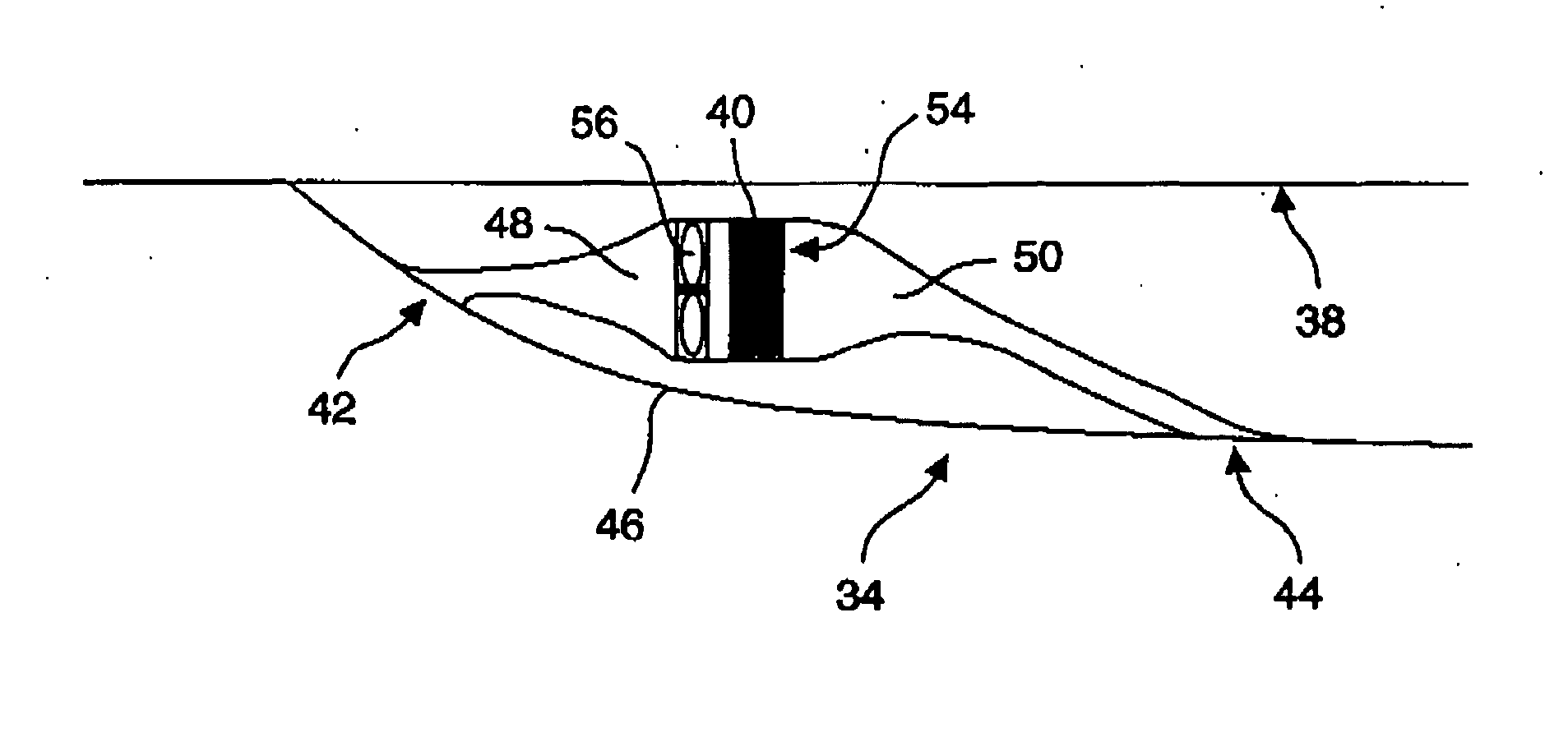
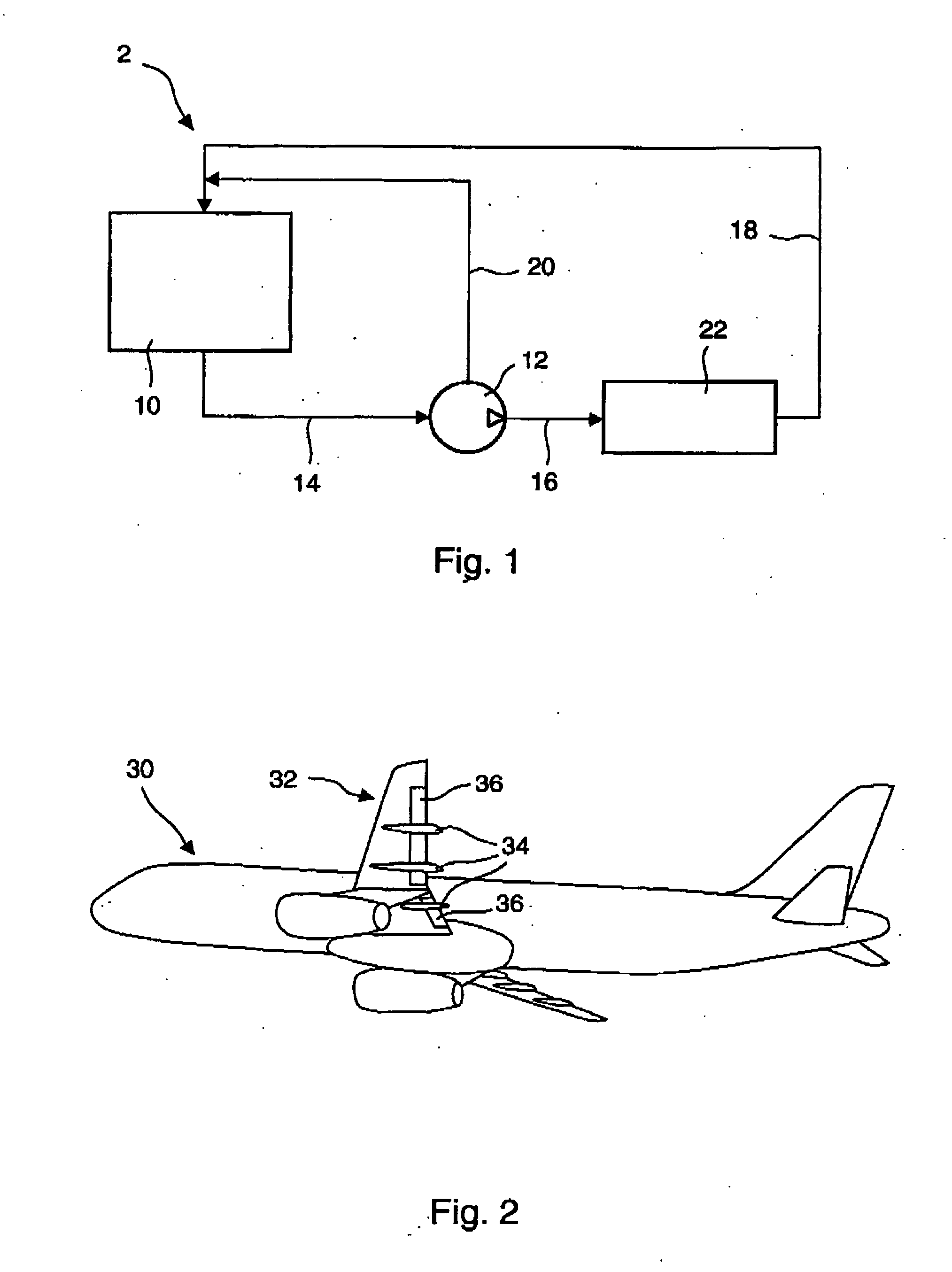
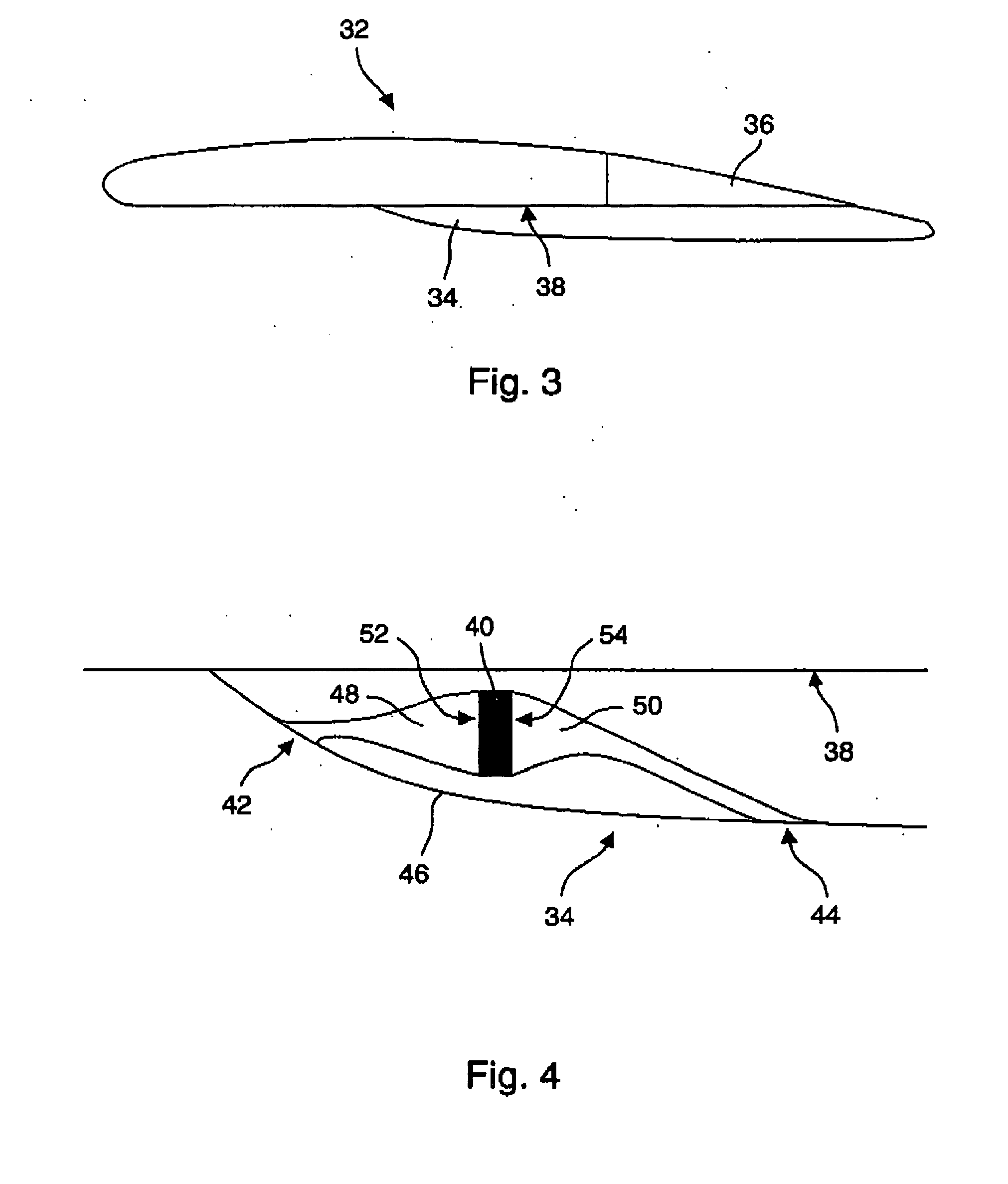
[0026] The aircraft fluid cooling system 30 in accordance with the invention, for which one embodiment is represented in FIG. 4, has an air heat exchanger 40 passed by said fluid to be cooled. This air heat exchanger 40 is installed in a housing located in a fairing 34 of the flap 36 guide rail connected to a wing 32 of this aircraft. Flap 36 guide rail fairings 34 connected to a wing 32 of an aircraft are represented from an exterior view in FIG. 2 and as a cross-section in FIG. 3. As is known, actuators, which are not shown, allow for moving these flaps 36 relative to the wing 32 of the aircraft 30 in such a way as to change the aerodynamic configuration of said aircraft. Said flap guide rails are generally located under the inner side 38 of the wing 32 and they are set to guide the movement of said flaps relative to this wing under the effect of said actuators. A fairing 34 is connected to each of said guide rails in such a way that these guide rails cause the minimum disruption ...


PUM


Abstract

The aircraft (30) fluid coolint system has an air heat exchanger (40) passed by this fluid, said air heat exchanger (40) including a means for the introduction of air (52) and an air exhaust means (54). This air heat exchanger (40) is installed in a housing located in a flap (36) guide rail fairing (34) connected to one wing (32) of this aircraft, said means for the introduction of air (52) in the air heat exchanger (40) being connected to an air inlet means (42) crossing the outer surface (46) of the fairing (34) and said air exhaust means (54) of said air heat exchanger (40) being connected to an air output means (44) opening outside said outer surface (46) in order that the air outside the aircraft (30) passes this air heat exchanger (40) to cool said fluid.

Description

TECHNICAL DOMAIN [0001] The invention concerns a system for cooling an aircraft fluid, in particular, a hydraulic fluid circulating on board this aircraft, said hydraulic fluid being for supplying one or more hydraulic actuators. The invention also concerns an aircraft equipped with such a system for cooling a fluid, in particular, a hydraulic fluid circulating on board this aircraft. PRIOR ART [0002] In an aircraft, there are generally one or more hydraulic fluid circuits, for supplying one or more hydraulic actuators such as, for example, hydraulic motors, or servo-controle, or pistons, etc. In the description which follows, such a hydraulic actuator which is supplied with hydraulic fluid, or which “consumes” the energy from the hydraulic fluid, shall be called the “consumer mechanism” or simply, “consumer”. [0003]FIG. 1 shows a conventional hydraulic fluid circuit, identified by the reference number 2. It includes, as is known per se, a hydraulic fluid reservoir 10, one or more h...

Claims


Application Information

Patent Timeline
IPC IPC(8): B60H1/00B64C7/00B64D33/10
CPCB64C7/00B64D33/10
Inventor MAHJOUB, FARES
Owner AIRBUS
Why Eureka
Try Eureka