
Point-of-use regulator for gas

a technology of gas point and use, which is applied in the direction of valves, respirators, transportation and packaging, etc., can solve the problems of correspondingly extensive assembly and the danger of unsealedness at the connection locations of individual elements, and achieve the effect of simple assembly and reduced danger of unsealedness

Inactive Publication Date: 2009-07-30
TESCOM EURO GMBH & CO KG
View PDF5 Cites 3 Cited by
  • Summary
  • Abstract
  • Description
  • Claims
  • Application Information

AI Technical Summary

Benefits of technology

[0004]It is the object of the invention to provide an improved point-of-use regulator for gas, which is constructed in a compact manner and is simple to assemble, as well as to reduce the danger of unsealedness (an unsealed state) between individual constituents of the point-of-use regulator for gas.
[0005]This object is achieved by a point-of-use regulator for gas according to the invention, which comprises, as a minimal combination, a pressure regulator as well as a metering valve. The pressure regulator serves for setting the pressure of the gas to be removed, and the metering valve for setting the throughput. Both elements are connected in series in the flow path, wherein the metering valve is preferably arranged downstream of the pressure regulator, I. e. at the exit side of the pressure regulator. According to the invention, the pressure regulator and the metering valve are integrated into a common valve block. I. e. the pressure regulator and the metering valve, according to the invention, form an integrated component. This has the advantage that on the one hand a compact construction may be achieved, and on the other hand it is not necessary to connect two individual parts, specifically the pressure regulator and the metering valve, to one another, for forming the point-of-use regulator for gas. A possible unsealedness in the connection location may be avoided in this manner. The compact construction furthermore provides the possibility of designing the appearance of the complete point-of-use regulator for gas in a more modern and attractive manner. Moreover, by way of this, one may achieve a clearer construction, which also improves the operability for the user. The integration of the metering valve and pressure regulator into a valve block, moreover, specifically permits a clear and easy to handle arrangement of the perspective operating elements for the pressure regulator and the metering valve.
[0006]According to a preferred embodiment, additionally a shut-off valve is integrated into the valve block, which serves for completely shutting off the gas supply. This is particularly preferred when the metering valve is not designed for the complete shut-off of the gas supply, and always permits a minimal throughput. The shut-off valve is preferably arranged in front of the pressure regulator in the flow direction, I. e. on the entry side of the pressure regulator. However, it is also possible to arrange the shut-off valve on the exit side of the pressure regulator, for example in the flow path between the pressure regulator and the metering valve, but also downstream of the metering valve. Thereby, the shut-off valve with the metering valve and the pressure regulator then form an integrated component in the common valve block, and this component permits a compact design of the complete point-of-use regulator for gas and moreover a clearer arrangement of the operating elements. In particular, all operating elements may be arranged closely to one another, so that a single-handed operation is possible without awkwardly having to grip around the point-of-use regulator for gas.

Problems solved by technology

Thereby, the disadvantages are the large construction on the one hand, and a correspondingly extensive assembly and the danger of unsealedness at the connection locations of the individual elements on the other hand.

Method used


Image

  • Point-of-use regulator for gas
  • Point-of-use regulator for gas
  • Point-of-use regulator for gas

Examples


Embodiment Construction

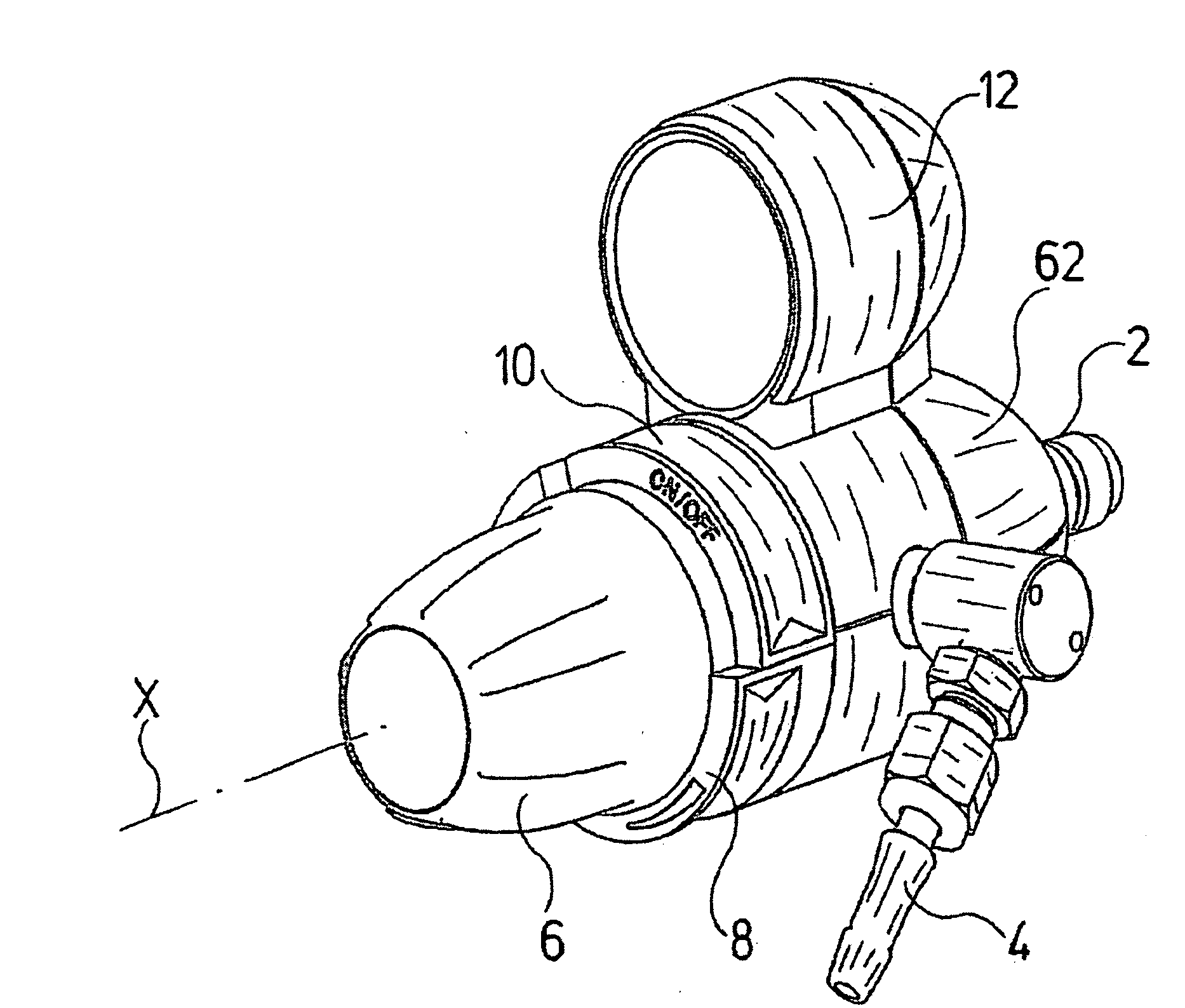
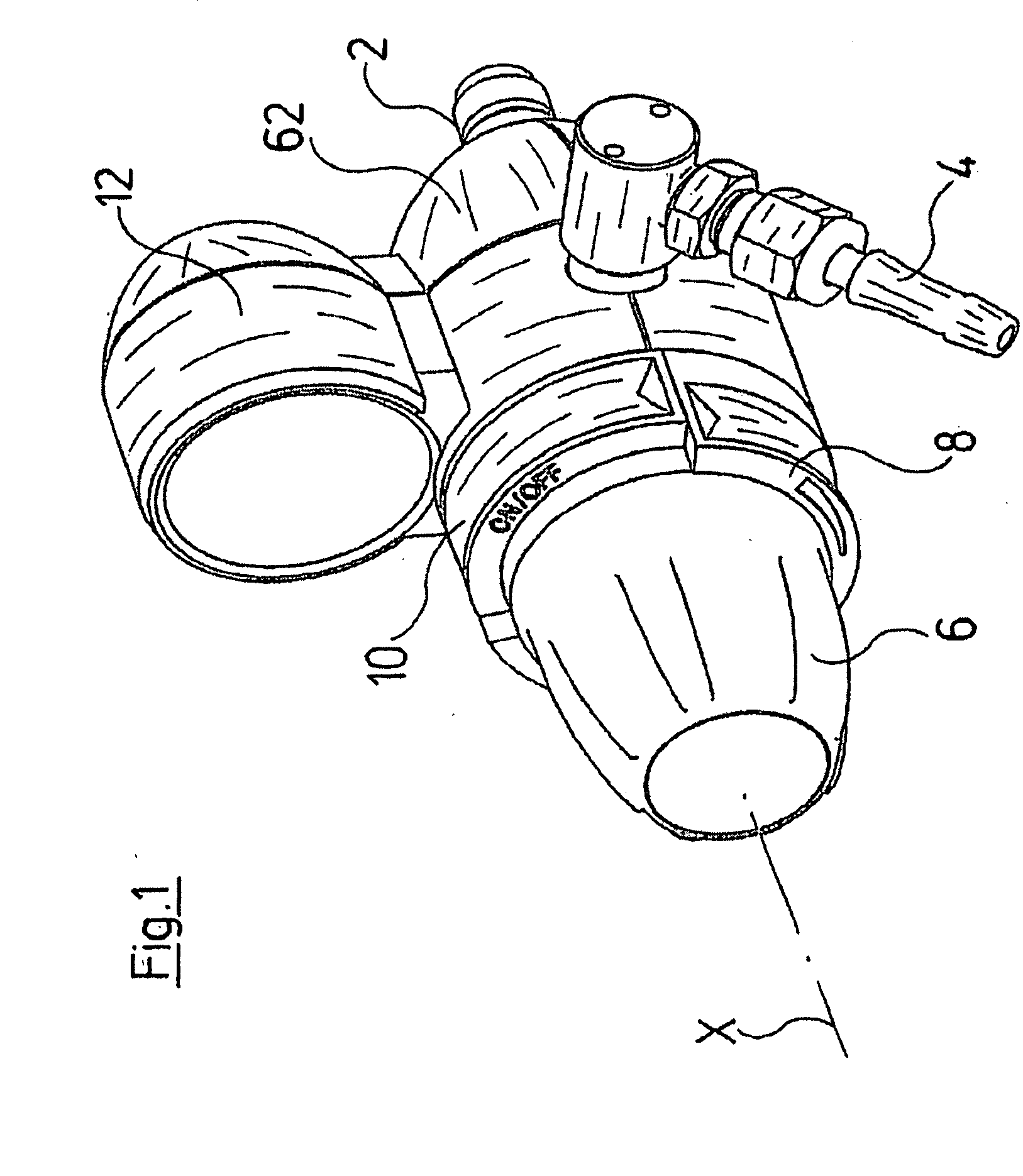
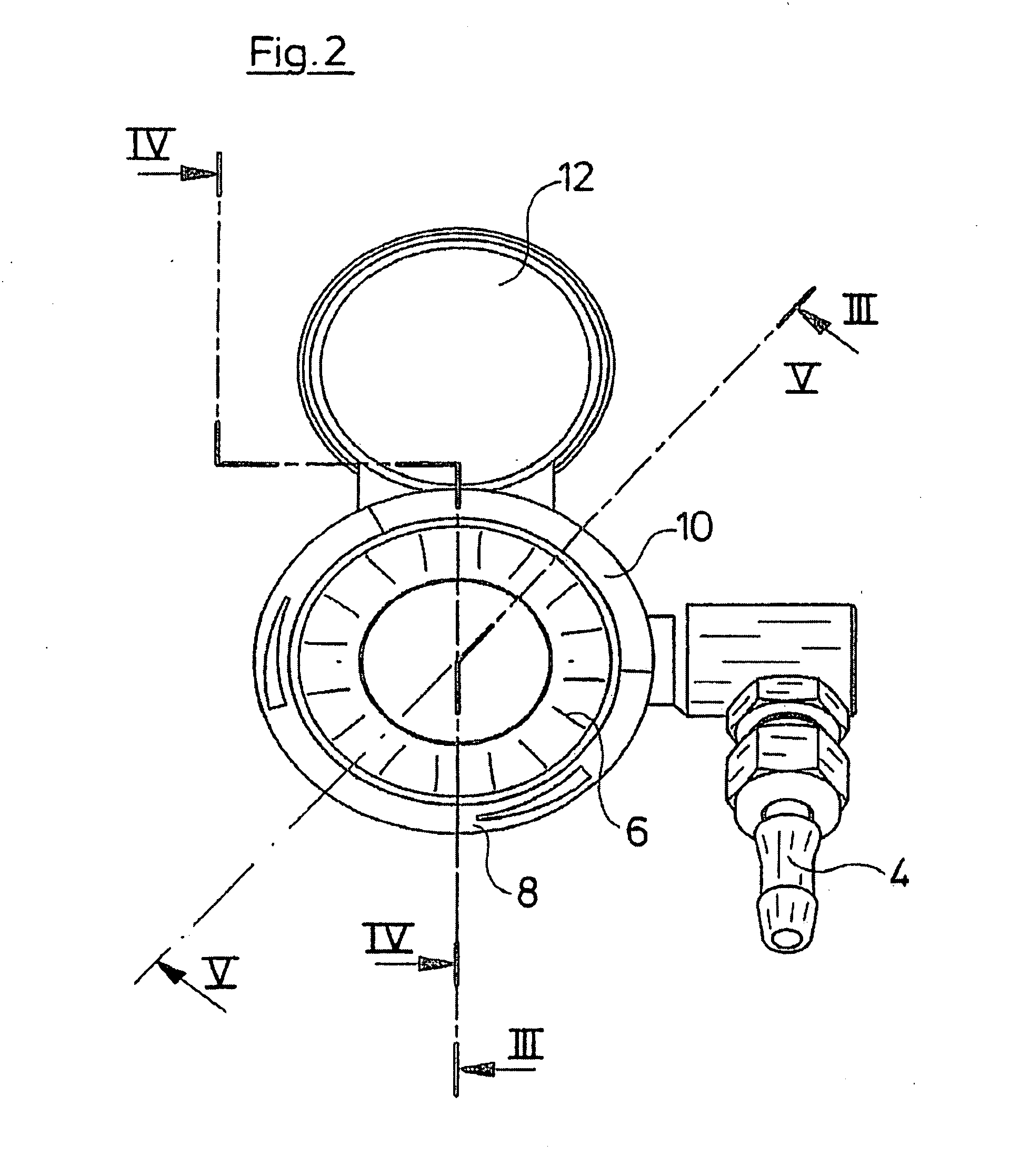
[0032]Referring to the drawings in particular, the shown point-of-use regulator for gas serves for the removal of gas from a gas source or a gas supply device. The point-of-use regulator for gas, for connecting to such a gas source or gas supply device, comprises a connection 2 which forms the gas entry, and a connection 4 which forms the gas exit. The connection 4 serves for the connection to external apparatus or installations which are to be supplied with gas, and this connection may also be designed differently than the manner of connecting to the connection flexible tubing, which is shown here. The point-of-use regulator for gas shown here, integrates three essential elements into a central component, specifically a pressure regulator, a metering valve and a shut-off valve, for which three actuation elements are formed or arranged on the outer side of the housing. This is firstly a hand wheel 6 for actuating the pressure regulator. The hand wheel 6 is arranged on the front side...


PUM


Abstract

A point-of-use regulator for gas is provided with a pressure regulator (16) and with a metering valve (14). The pressure regulator (18) and the metering valve (14) are integrated into a common valve block (18).

Description

CROSS REFERENCE TO RELATED APPLICATIONS[0001]This application claims the benefit of priority under 35 U.S.C. § 119 of European Patent Application EP 08 001 466.5 filed Jan. 26, 2008, the entire contents of which are incorporated herein by reference.FIELD OF THE INVENTION[0002]The invention relates to a point-of-use regulator for gas.BACKGROUND OF THE INVENTION[0003]Point-of-use regulators for gas, are known for example in hospitals or laboratories, to which the most varied of apparatus and appliances may be connected for their gas supply. At the other side, the point-of-use regulator for gas is in connection for example with a central gas supply. Often, the most varied of elements such as pressure regulators, manometers, shut-off valves and metering valves are required on such point-of-use regulators for gas, in order to shut off the gas supply and to regulate it with regard to pressure and throughput. The respective elements for this are arranged one after the other and connected t...

Claims


Application Information

Patent Timeline
Patent Type & Authority Applications(United States)
IPC IPC(8): F16K31/12
CPCA61M16/20A61M16/207G01N1/22Y10T137/7793
Inventor BASLER, CHRISTIAN
Owner TESCOM EURO GMBH & CO KG
Learn More