Aircraft fluid cooling system and aircraft provided with said system

a fluid cooling system and aircraft technology, applied in vehicle heating/cooling devices, transportation and packaging, railway components, etc., can solve the problems of affecting the functioning of the hydraulic circuit, affecting so as to improve the cooling effect of the fluid, and the effect of reducing the throughput of air

Inactive Publication Date: 2009-04-21
AIRBUS
View PDF14 Cites 31 Cited by
  • Summary
  • Abstract
  • Description
  • Claims
  • Application Information

AI Technical Summary

Benefits of technology

[0012]This aircraft fluid cooling device allows for discharging the heat from the cooling of said fluid into the air outside this aircraft. In so doing, it benefits from the dynamic flow of air around the aircraft.
[0014]Advantageously, the aircraft fluid cooling system that is the subject of this invention has at least one fan for ensuring a minimum throughput of air in the air heat exchanger. This fan allows for ensuring and improving the cooling of said fluid by increasing the throughput of air through the air heat exchanger, in particular when the aircraft speed is nil (aircraft on the ground) or less than a predetermined value (e.g. during the take-off and landing phases). This fan can advantageously be installed upstream, depending on the direction of the air circulation, of the air heat exchanger or downstream of this air heat exchanger.

Problems solved by technology

Generally, it is estimated that approximately 10% to 15% of the total power available to the pumps is lost as a result of the existence of these internal leaks, and that this power fraction is turned into heat.
Such heating of the hydraulic fluid has a harmful effect on the functioning of the hydraulic circuit.
In fact, this heating results in the degradation of the hydraulic fluid, and thus in a reduction in its performance.
In particular, heating of the fluid may lead to an increase in the acidity of said fluid, which can cause deterioration of the consumer mechanisms of said hydraulic fluid.
This heating may also lead to a deterioration of the joints in the hydraulic circuit, and consequently, external leaks on the hydraulic circuit.
But for aircraft that are compact with regard to the hydraulic power installed, i.e. which have short supply pipes in comparison to the hydraulic power available, the natural dissipation of heat is still insufficient.
This second solution was able to be used on old aircraft, but it has no longer been acceptable since new safety regulations came into effect, which stipulate minimising any heat transfers to fuel.
Consequently, this second solution may no longer be used, as it does not allow for controlling the temperature of the fuel, whether inside the fuel tanks or as it enters the engines, and consequently, neither of the statutory conditions are respected.

Method used


Image

  • Aircraft fluid cooling system and aircraft provided with said system
  • Aircraft fluid cooling system and aircraft provided with said system
  • Aircraft fluid cooling system and aircraft provided with said system

Examples


Embodiment Construction

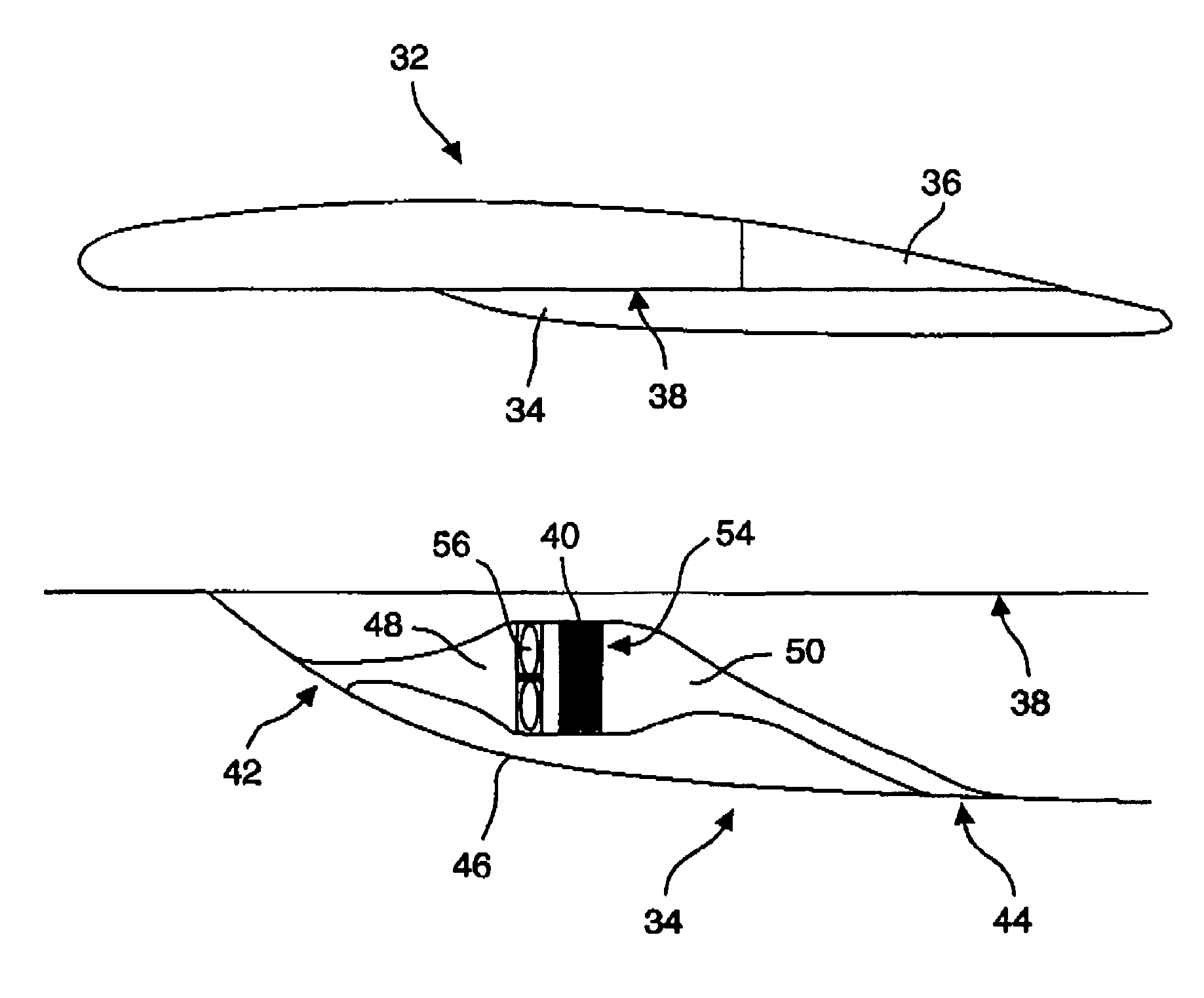
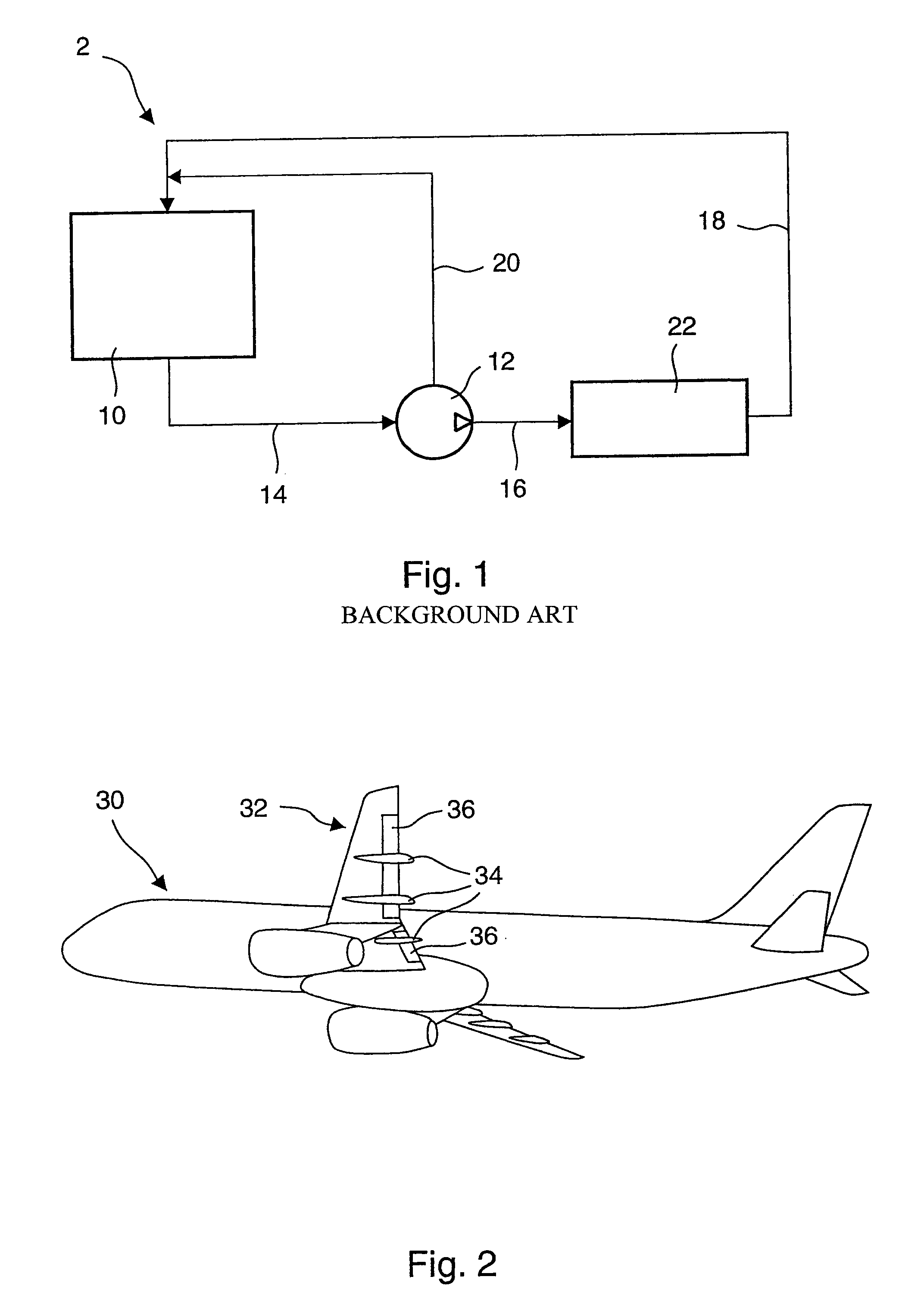
[0028]The aircraft fluid cooling system 30 in accordance with the invention, for which one embodiment is represented in FIG. 4, has an air heat exchanger 40 passed by said fluid to be cooled. This air heat exchanger 40 is installed in a housing located in a fairing 34 of the flap 36 guide rail connected to a wing 32 of this aircraft. Flap 36 guide rail fairings 34 connected to a wing 32 of an aircraft are represented from an exterior view in FIG. 2 and as a cross-section in FIG. 3. As is known, actuators, which are not shown, allow for moving these flaps 36 relative to the wing 32 of the aircraft 30 in such a way as to change the aerodynamic configuration of said aircraft. Said flap guide rails are generally located under the inner side 38 of the wing 32 and they are set to guide the movement of said flaps relative to this wing under the effect of said actuators. A fairing 34 is connected to each of said guide rails in such a way that these guide rails cause the minimum disruption p...


PUM


Abstract

An aircraft fluid cooling system has an air heat exchanger passed by this fluid, the air heat exchanger including a structure for introduction of air and an air exhaust. The air heat exchanger is installed in a housing located in a flap guide rail fairing connected to one wing of the aircraft. The structure for introduction of air in the air heat exchanger is connected to an air inlet crossing an outer surface of the flap guide rail fairing and an air exhaust of the air heat exchanger is connected to an air output opening outside the outer surface such that air outside the aircraft passes this air heat exchanger to cool the fluid.

Description

TECHNICAL DOMAIN[0001]The invention concerns a system for cooling an aircraft fluid, in particular, a hydraulic fluid circulating on board this aircraft, said hydraulic fluid being for supplying one or more hydraulic actuators. The invention also concerns an aircraft equipped with such a system for cooling a fluid, in particular, a hydraulic fluid circulating on board this aircraft.PRIOR ART[0002]In an aircraft, there are generally one or more hydraulic fluid circuits, for supplying one or more hydraulic actuators such as, for example, hydraulic motors, or servo-controls, or pistons, etc. In the description which follows, such a hydraulic actuator which is supplied with hydraulic fluid, or which “consumes” the energy from the hydraulic fluid, shall be called the “consumer mechanism” or simply, “consumer”.[0003]FIG. 1 shows a conventional hydraulic fluid circuit, identified by the reference number 2. It includes, as is known per se, a hydraulic fluid reservoir 10, one or more hydraul...

Claims


Application Information

Patent Timeline
Patent Type & Authority Patents(United States)
IPC IPC(8): B64D33/10B64C7/00
CPCB64C7/00B64D33/10
Inventor MAHJOUB, FARES
Owner AIRBUS
Why Eureka
Try Eureka